Tool sharpener

A knife grinder and grinding wheel technology, applied in grinding/polishing equipment, grinding/polishing safety devices, other manufacturing equipment/tools, etc., can solve problems such as difficult to master, complex structure of knife grinder, easy to be injured, etc. To achieve the effect of preventing splashing around

Inactive Publication Date: 2016-08-31
江浩
View PDF6 Cites 5 Cited by
  • Summary
  • Abstract
  • Description
  • Claims
  • Application Information

AI Technical Summary

Problems solved by technology

This method is not easy to master, if you are not skilled, it is easy to get injured
In order to facilitate sharpening, there are some knife sharpening machines on the market, but these knife sharpening machines are either too complicated in structure, or difficult to master, and are not suitable for popular use by the general public.

Method used


Image

  • Tool sharpener
  • Tool sharpener
  • Tool sharpener

Examples


Embodiment 1

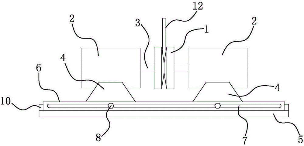
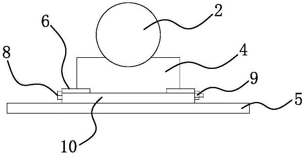
[0023] like figure 1 shown, combined with figure 2 As shown, the knife grinder of the present invention comprises two oppositely arranged emery wheels 1, and the opposite wheel surfaces of the two emery wheels 1 are conical, and the two emery wheels 1 are respectively driven by a motor 2, and when the motor 2 drives the emery wheel 1 to rotate, the two emery wheels The rotation direction of grinding wheel 1 is opposite. When in use, the cutting edge of the cutter 12 is placed between the conical surfaces of the two grinding wheels 1. Since the rotation directions of the two grinding wheels 1 are opposite, the cutter 12 is simultaneously subjected to the frictional force applied by the grinding wheels 1 in two opposite directions. Now the cutter 12 is force-balanced in the horizontal direction, and the cutter 12 can be sharpened as long as the cutter 12 is reciprocated two or three times along a straight line by hand.

[0024] The specific way that the motor 2 drives the gri...

Embodiment 2

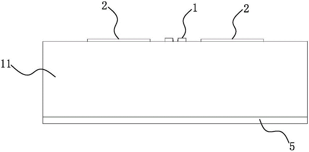
[0032] The difference between the present embodiment and the first embodiment is that an arc-shaped baffle 11 is provided on both sides of the slide rail 6, and this embodiment will be described in detail below.

[0033] like image 3 shown, combined with Figure 4 , 5 As shown, the knife grinder of the present invention comprises two oppositely arranged emery wheels 1, and the opposite wheel surfaces of the two emery wheels 1 are conical, and the two emery wheels 1 are respectively driven by a motor 2, and when the motor 2 drives the emery wheel 1 to rotate, the two emery wheels The rotation direction of grinding wheel 1 is opposite. When in use, the cutting edge of the cutter 12 is placed between the conical surfaces of the two grinding wheels 1. Since the rotation directions of the two grinding wheels 1 are opposite, the cutter 12 is simultaneously subjected to the frictional force applied by the grinding wheels 1 in two opposite directions. Now the cutter 12 is force-ba...


PUM


Abstract

The invention relates to a grinder for grinding tools, in particular to a tool sharpener which is simple in structure and easy and convenient to operate. The tool sharpener comprises two oppositely arranged grinding wheels (1) with opposite wheel surfaces being conical. The two grinding wheels (1) are driven by motors (2) correspondingly, and when the motors (2) drive the grinding wheels (1) to rotate, the two grinding wheels (1) are opposite in rotation direction.

Description

technical field [0001] The invention relates to a grinding tool, in particular to a grinding tool for grinding tools. Background technique [0002] Knife sharpening is a kind of technical work, especially for kitchen knives. The traditional method of sharpening knives is to put the knife on the whetstone, press the knife with your hands so that it is close to the whetstone, and then rub it back and forth. This method is not easy to master, and if you are not skilled, it is easy to get injured. In order to sharpen the knife conveniently, there are some knife sharpening machines on the market, but these knife sharpening machines are either too complicated in structure, or are not easy to master, and are not suitable for popular use by the common people. Contents of the invention [0003] The technical problem to be solved by the present invention is to provide a sharpening machine with simple structure and easy operation. [0004] The knife grinder of the present invention...

Claims


Application Information

Patent Timeline
Patent Type & Authority Applications(China)
IPC IPC(8): B24B3/54B24B55/00
CPCB24B3/54B24B55/00
Inventor 江浩
Owner 江浩
Why Eureka
Try Eureka