Combined type fiber loop framework for fiber-optic gyroscope

A technology of fiber optic ring skeleton and fiber optic gyroscope, which is applied in Sagnac effect gyroscopes, gyroscopes/steering sensing equipment, measuring devices, etc., and can solve the problem of increasing the radial temperature gradient effect of fiber optic rings and affecting the temperature performance of fiber optic gyroscopes , lower pass rate of optical fiber ring, etc., to achieve the effect of reduced radial temperature gradient effect, simple structure, and reduced number of layers of optical fiber winding

Inactive Publication Date: 2016-08-31
SHAANXI BAOCHENG AVIATION INSTR
View PDF9 Cites 5 Cited by
  • Summary
  • Abstract
  • Description
  • Claims
  • Application Information

AI Technical Summary

Problems solved by technology

[0002] The fiber optic gyroscope is a new type of inertial device, which is based on the Sagnac effect of light, and the fiber optic ring is a component used in the fiber optic gyroscope to sense the Sagnac phase difference between two beams of opposite light waves caused by the input angular velocity. It directly affects the performance of the fiber optic gyroscope. With the movement of the carrier, the light propagates in two different directions in the fiber optic ring, and the formed optical path difference realizes the function of the gyroscope through digital demodulation of the circuit. In addition, the fiber optic ring is the key to the fiber optic gyroscope. The skeleton of the component not only plays a supporting role, but also directly affects the disk installation and overall structural design of the optical system. Therefore, the design of the fiber optic ring skeleton directly determines the reliability of the performance of the fiber optic gyroscope. Especially for high-precision fiber optic gyroscopes, usually winding The length of the optical fiber is more than 1km. As the number of winding turns increases, it will bring great difficulties to the winding personnel under the premise of ensuring the overall arrangement, no climbing layer, and consistent stress. At the same time, the qualified rate of the optical fiber ring will decrease and the cost will increase. Second, due to the increase in the number of winding layers, the radial temperature gradient effect of the fiber optic ring increases, thereby affecting the temperature performance of the fiber optic gyroscope; finally, the design of the fiber optic ring skeleton may cause the height of the fiber optic gyroscope to increase, causing the center of mass to rise, while The fiber optic gyro is generally fixed on the base by screws, which affects its vibration, so it is necessary to improve

Method used


Image

  • Combined type fiber loop framework for fiber-optic gyroscope
  • Combined type fiber loop framework for fiber-optic gyroscope
  • Combined type fiber loop framework for fiber-optic gyroscope

Examples


Embodiment Construction

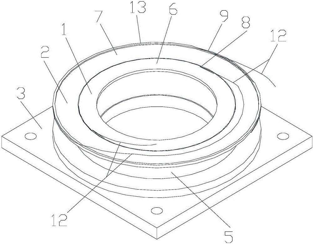
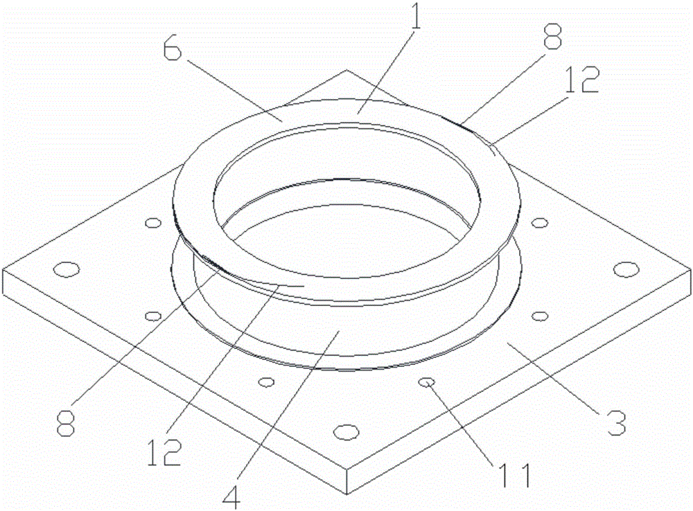
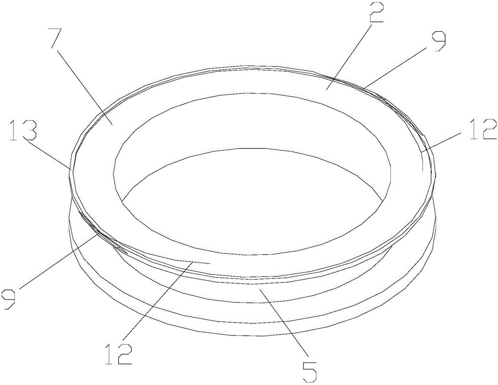
[0018] Attached below Figure 1-5 An embodiment of the present invention is described.

[0019] A combined fiber optic ring skeleton for a fiber optic gyroscope, comprising an inner fiber optic ring skeleton 1, an outer fiber optic ring skeleton 2 and a mounting plate 3, the inner fiber optic ring skeleton 1 and the outer fiber optic ring skeleton 2 both having an I-shaped ring structure and The lower end surface of the inner fiber ring frame 1 is fixed on the mounting plate 3, and the upper end faces of the inner fiber ring frame 1 and the outer fiber ring frame 2 are respectively the fiber optic disk installation surface I6 and the fiber optic disk installation surface II7, and the inner fiber optic ring skeleton 1 The outer ring wall between the upper and lower end faces of the outer fiber ring skeleton 2 is the fiber winding torus I4 and the fiber winding torus II5 respectively, and the fiber winding torus I4 and the fiber winding torus II5 are equipped with four The opti...


PUM


Abstract

The invention provides a combined type fiber loop framework for a fiber-optic gyroscope. The combined type fiber loop framework is provided with an internal fiber loop framework body, an external fiber loop framework body and a mounting plate. The internal fiber loop framework body and the external fiber framework body are both of I-shaped loop structures, and the lower end face of the internal fiber loop framework body is fixed to the mounting plate. An optical fiber winding loop face I and an optical fiber winding loop face II are both provided with optical fibers wound in a quadrupolar symmetry mode, and gluing discs at the two optical fiber outlet ends of the optical fiber on each of the optical fiber winding loop face I and the optical fiber winding loop face II are mounted on the optical fiber winding loop face I and the optical fiber winding loop face. The internal fiber loop framework body is embedded into a center hole of the external fiber loop framework body, and the lower end of the external fiber loop framework body is fixed to the mounting plate. The high-precision fiber loop winding length is distributed to the internal fiber loop framework body and the external fiber loop framework body, the number of winding turns is reduced, the winding difficulty for staff is lowered, and the yield is increased; meanwhile, quadrupolar symmetry optical fiber winding is adopted, so that the influence of the temperature gradient effect on the performance of the fiber-optic gyroscope is effectively reduced, the vibration performance of the fiber-optic gyroscope is improved, the structure is simple, and operation is easy.

Description

technical field [0001] The invention belongs to the technical field of fiber optic gyroscopes, and in particular relates to a combined fiber optic ring frame used for fiber optic gyroscopes. Background technique [0002] The fiber optic gyroscope is a new type of inertial device, which is based on the Sagnac effect of light. The fiber optic ring is a component used in the fiber optic gyroscope to sense the Sagnac phase difference between two beams of opposite light waves caused by the input angular velocity. It directly affects the performance of the fiber optic gyroscope. With the movement of the carrier, the light propagates in two different directions in the fiber optic ring, and the formed optical path difference realizes the function of the gyroscope through digital demodulation of the circuit. In addition, the fiber optic ring is the key to the fiber optic gyroscope. Components, whose skeleton not only plays a supporting role, but also directly affects the disk install...

Claims


Application Information

Patent Timeline
Patent Type & Authority Applications(China)
IPC IPC(8): G01C19/72
CPCG01C19/722
Inventor 杨鹏何虹锋
Owner SHAANXI BAOCHENG AVIATION INSTR
Why Eureka
Try Eureka