Optical fiber collimating device and assembling method thereof

A technology of optical fiber alignment and optical fiber, applied in the direction of light guides, optics, optical components, etc., can solve the problems of increasing V-shaped grooves and movable workbench processing difficulties and high processing costs, and achieves simple structure, reduced processing costs, and convenient operation Effect

Active Publication Date: 2016-08-31
THE 41ST INST OF CHINA ELECTRONICS TECH GRP
View PDF7 Cites 3 Cited by
  • Summary
  • Abstract
  • Description
  • Claims
  • Application Information

AI Technical Summary

Problems solved by technology

This not only requires strict requirements on the accuracy of the V-shaped groove itself, but also has strict requirements on the installation reference plane between the V-shaped groove and the movable workbench. Tolerance and shape tolerance, which increases the processing difficulty of V-shaped groove and movable table, and the processing cost is higher

Method used


Image

  • Optical fiber collimating device and assembling method thereof
  • Optical fiber collimating device and assembling method thereof

Examples


Embodiment Construction

[0018] The specific implementation of the present invention will be further described below in conjunction with the accompanying drawings and specific embodiments:

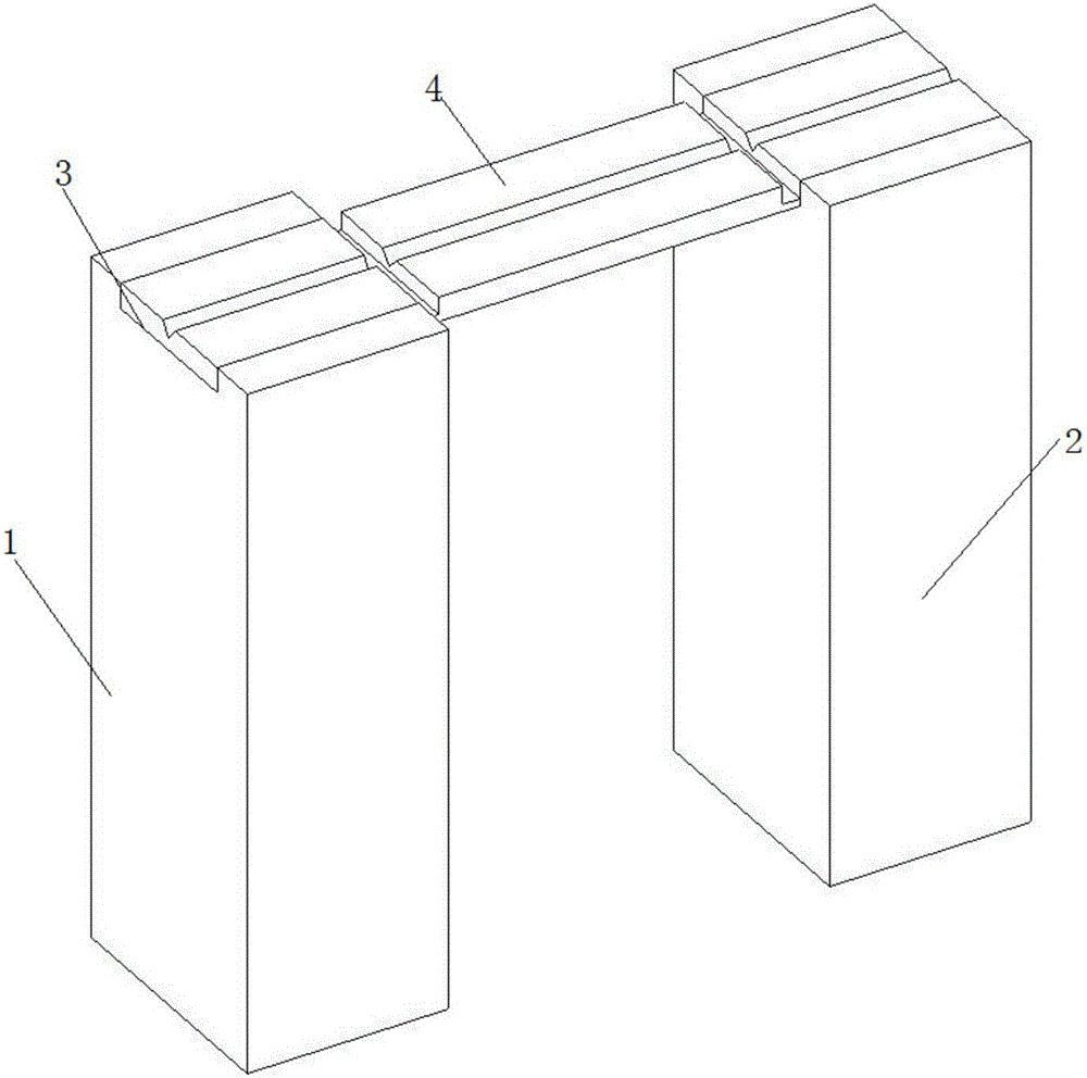
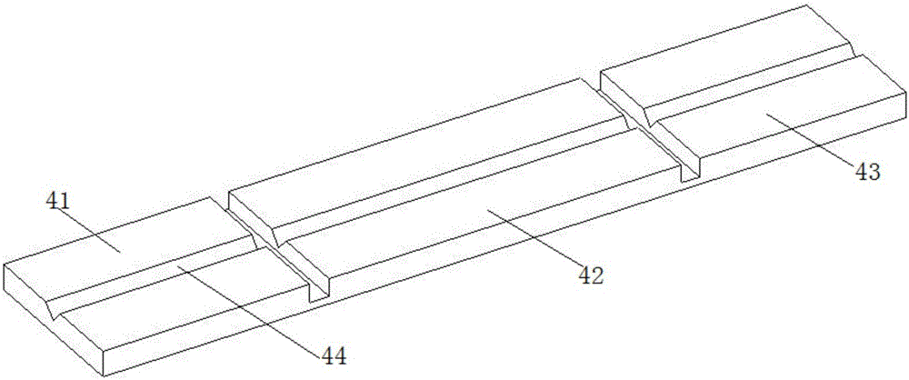
[0019] Such as Figure 1-2 As shown, an optical fiber collimation device includes a substrate 4 and a substrate support table. The substrate 4 is made of silicon wafer or ceramic material. The substrate 4 is set on the substrate support table. The substrate 4 includes a first fiber carrying portion 41 and an intermediate interconnection. The first optical fiber carrying portion 41, the intermediate interconnecting portion 42 and the second optical fiber carrying portion 43 are processed on the substrate 4 by photolithography or molding followed by auxiliary processing methods. A V-shaped groove 44 intersecting and having a V-shaped cross section is provided at the central axis of the portion 41, the intermediate interconnecting portion 42 and the second fiber carrying portion 43.

[0020] The substrate support table i...


PUM


Abstract

The invention discloses an optical fiber collimating device and an assembling method thereof and especially relates to the optical fiber collimating technology field. In existing optical fiber welding operation, a ''V''-shaped groove used for fixing an optical fiber is movably connected to a movable workbench, and an installation reference surface of the ''V''-shaped groove and the movable workbench is difficult to realize accurate collimation connection. By using the device and the method of the invention, the above problems are solved. The optical fiber collimating device comprises a substrate and a substrate support bench. The substrate is made of a silicon wafer or a ceramic material. The substrate is arranged on the substrate support bench. The substrate comprises a first optical fiber carrying portion, a middle interconnection portion and a second optical fiber carrying portion. Central axes of the first optical fiber carrying portion, the middle interconnection portion and the second optical fiber carrying portion are provided with V-shaped grooves which pass through each other and have V-shaped cross sections. The substrate support bench comprises a first workbench and a second workbench. Shapes of the first workbench and the second workbench are similar and the first workbench and the second workbench are parallel to each other.

Description

Technical field [0001] The invention belongs to the technical field of optical fiber collimation, and specifically relates to an optical fiber collimating device and an assembly method thereof. Background technique [0002] At present, in optical fiber fusion splicing applications, in order to achieve low-loss splicing, the fibers to be spliced ​​on both sides must be accurately aligned, that is, the V-grooves of the fibers on both sides that carry the fiber must be accurately aligned. Generally, the V-shaped grooves on both sides are made separately and installed in the movable workbenches on both sides. This requires not only strict requirements on the accuracy of the V-groove itself, but also strict requirements on the installation reference surface of the V-groove and the movable table. The size of the fiber-carrying part of the V-groove and the installation reference surface of the V-groove must be guaranteed. Tolerances and geometric tolerances, which increase the difficul...

Claims


Application Information

Patent Timeline
Patent Type & Authority Applications(China)
IPC IPC(8): G02B6/255
CPCG02B6/2555
Inventor 姚吉椽尚守锋杨小光田军
Owner THE 41ST INST OF CHINA ELECTRONICS TECH GRP
Why Eureka
Try Eureka