
Circularly-polarized antenna and wireless communication device thereof

A circularly polarized antenna and transmission line technology, applied in the field of circularly polarized antennas and wireless communication equipment, can solve problems such as poor positioning performance, difficulty in installing radiation performance antennas, and affecting customer experience, so as to enhance radiation performance and realize circular polarization. Polarized radiation, the effect of improving user experience

Inactive Publication Date: 2016-08-31
SHANGHAI AMPHENOL AIRWAVE COMM ELECTRONICS CO LTD
View PDF5 Cites 12 Cited by
  • Summary
  • Abstract
  • Description
  • Claims
  • Application Information

AI Technical Summary

Problems solved by technology

However, due to the limited size of smart devices, the relevant functions or performance of the products cannot well meet customer needs. For example, most smart watches on the market do not have GPS (Global Positioning System) positioning functions. Although some have positioning functions, their The poor positioning performance is due to the limited size of the watch, and it is difficult to design a circularly polarized GPS antenna on it. Currently, smart watch antennas with GPS functions use linear polarization, resulting in extremely poor reception efficiency and affecting customer experience.
The same is true for other smart devices. Due to volume limitations, it is difficult to install antennas with better radiation performance, resulting in related functions or performance of the product that cannot meet customer needs.

Method used


Image

  • Circularly-polarized antenna and wireless communication device thereof
  • Circularly-polarized antenna and wireless communication device thereof
  • Circularly-polarized antenna and wireless communication device thereof

Examples


Embodiment Construction

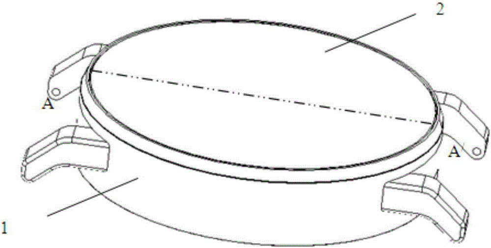
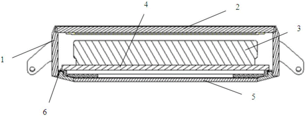
[0040]In order to make the above objects, features and advantages of the present invention more clearly understood, the specific embodiments of the present invention will be described in detail below with reference to the accompanying drawings.

[0041] In the following description, numerous specific details are set forth in order to provide a thorough understanding of the present invention. However, the present invention can be implemented in many other ways different from those described herein, and those skilled in the art can make similar promotions without departing from the connotation of the present invention. Therefore, the present invention is not limited by the specific implementation disclosed below.

[0042] The circularly polarized antenna of the present invention can be used in any wireless communication device that can transmit or receive circularly polarized waves. Since the volume can be made small, it is especially suitable for use in wearable smart devices. T...


PUM


Abstract

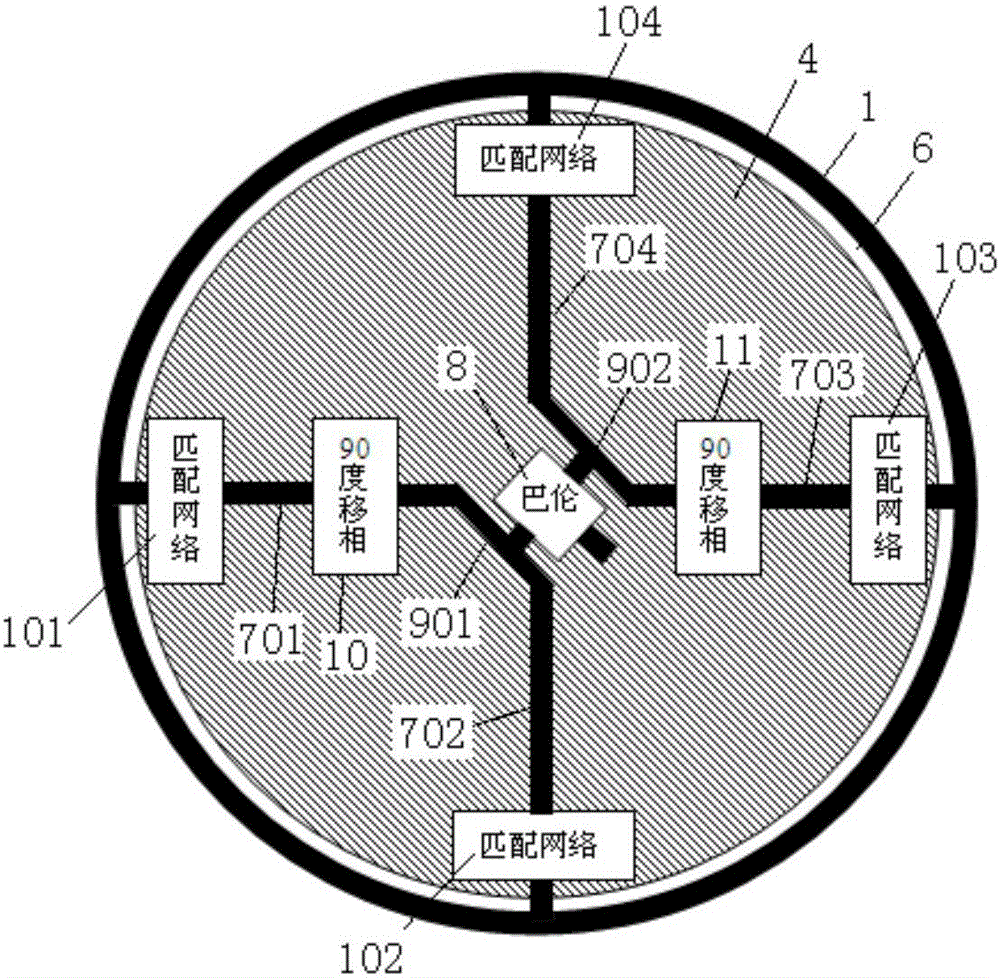
The invention provides a circularly-polarized antenna. With a way of balanced differential signal driving, a first transmission line and a second transmission line are driven by positive signals; and a third transmission line and a fourth transmission line are driven by negative signals. A phase difference is configured reasonably; and thus a positive-90-degree or negative-90-degree phase difference is formed between the first transmission line and the second transmission line; and a positive-90-degree or negative-90-degree phase difference is formed between the third transmission line and a fourth transmission line. When an antenna transmits a signal, the first transmission line and the third transmission line can form vertically polarized waves by radiation at a radiating body under the drive of balanced differential signals; and the second transmission line and the fourth transmission line can form horizontally polarized waves by radiation at the radiating body under the drive of balanced differential signals. Because of the phase differences of the transmission lines, the vertically polarized waves and the horizontally polarized waves are orthogonal mutually, thereby forming a circularly polarized wave by a synthesis and thus realizing circularly-polarized radiation of the antenna. The circularly-polarized antenna is suitable for various wireless communication devices capable of carrying out receiving or transmitting, especially for a wearable electronic device; and the user experience can be improved.

Description

technical field [0001] The present invention relates to the technical field of antennas, in particular to a circularly polarized antenna and a wireless communication device thereof. Background technique [0002] Smart devices are developing rapidly, products are changing with each passing day, and smart phones have basically become popular. Now, wearable smart devices have become the new favorite of manufacturers and a new hot spot in the consumption of electronic products. From the Apple Watch to the Xiaomi Mi Band, wearable smart devices are gradually being accepted and loved by the public. However, due to the limited size of smart devices, the relevant functions or performance of the products cannot meet the needs of customers. For example, most smart watches on the market do not have GPS (Global Positioning System) positioning functions. Although some have positioning functions, their The poor positioning performance is due to the limited size of the watch, and it is di...

Claims


Application Information

Patent Timeline
Patent Type & Authority Applications(China)
IPC IPC(8): H01Q1/50H01Q15/24H01Q1/27G04R60/06
CPCH01Q1/27H01Q15/24H01Q1/50G04R60/06H01Q1/273
Inventor 胡沥徐利军
Owner SHANGHAI AMPHENOL AIRWAVE COMM ELECTRONICS CO LTD
Learn More