
Omni-directional GPS (global positioning system) patch antenna

A patch antenna and antenna technology, applied in the field of communication antennas, to achieve the effects of large signal transmission/reception range, simple design and low profile

Inactive Publication Date: 2018-09-18
SUN YAT SEN UNIV
View PDF1 Cites 0 Cited by
  • Summary
  • Abstract
  • Description
  • Claims
  • Application Information

AI Technical Summary

Problems solved by technology

Since the radiation pattern of the low-order mode is directional, the GPS patch antenna realized by the above-mentioned prior art can only produce directional circularly polarized radiation

Method used


Image

  • Omni-directional GPS (global positioning system) patch antenna
  • Omni-directional GPS (global positioning system) patch antenna
  • Omni-directional GPS (global positioning system) patch antenna

Examples


Embodiment Construction

[0030] The technical solutions in the embodiments of the present invention will be clearly and completely described below with reference to the accompanying drawings in the embodiments of the present invention. Obviously, the described embodiments are only a part of the embodiments of the present invention, not all of the embodiments. Based on the embodiments of the present invention, all other embodiments obtained by those of ordinary skill in the art without creative efforts shall fall within the protection scope of the present invention.

[0031] It should be noted that if there are directional indications (such as up, down, left, right, front, back, etc.) involved in the embodiments of the present invention, the directional indications are only used to explain a certain posture (as shown in the accompanying drawings). If the specific posture changes, the directional indication also changes accordingly.

[0032] In addition, if there are descriptions involving "first", "sec...


PUM


Abstract

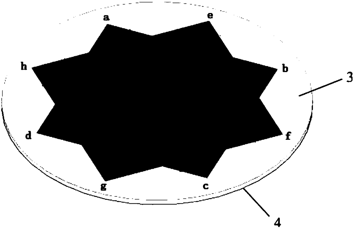
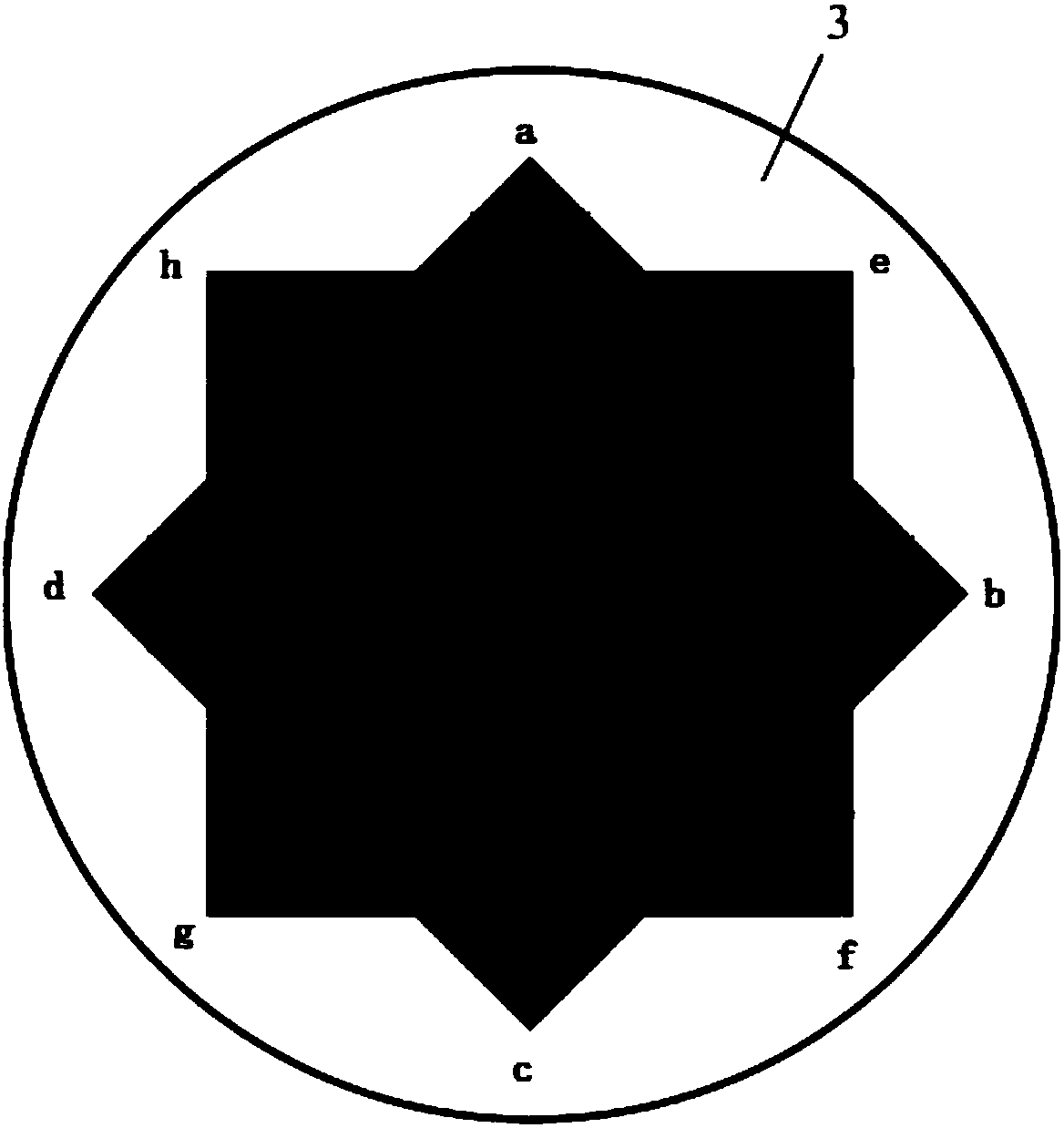
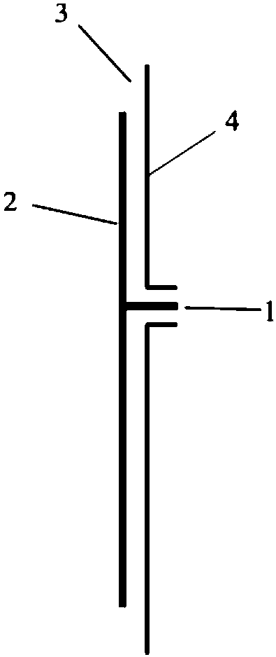
The invention provides an omni-directional GPS patch antenna, which comprises a radiation patch, a metal floor, a feeding probe and a dielectric slab. The radiation patch and the metal floor are arranged on the upper surface and the lower surface of the dielectric slab respectively. The feeding probe penetrates through the dielectric slab and is connected with the radiation patch. The radiation patch and the dielectric slab are arranged concentrically, and form a closed symmetrical polygon with unequal edges. According to the invention, the circular polarization radiation in all directions isrealized, and the larger signal emitting / receiving range is provided.

Description

technical field [0001] The invention relates to the field of communication antennas, in particular to an omnidirectional GPS patch antenna. Background technique [0002] The traditional GPS patch antenna is a circularly polarized antenna and a directional antenna, that is, it can only radiate circularly polarized waves in one direction. For a directional GPS antenna mounted on a ground terminal (such as a vehicle), its main beam may deviate from the incoming wave direction of the GPS signal due to the movement of the ground terminal, resulting in poor GPS signal reception quality. Therefore, there is a need for a GPS antenna that can realize omnidirectional circularly polarized radiation, so that a ground terminal in motion can send / receive signals in all directions of 360 degrees. [0003] Common implementations of GPS patch antennas include: [0004] 1) Cut corners on the patch antenna; [0005] 2) Etch the inclined groove on the patch antenna; [0006] 3) Use an oval ...

Claims


Application Information

Patent Timeline
Patent Type & Authority Applications(China)
IPC IPC(8): H01Q1/38H01Q1/48H01Q1/50
Inventor 刘菊华史煜仲
Owner SUN YAT SEN UNIV
Learn More