
Circularly polarized FP resonant cavity antenna

A resonant cavity antenna and circular polarization technology, which is applied in the direction of resonant antenna, antenna, antenna grounding switch structure connection, etc., can solve the difficult problem of beam deflection, fixed radiation direction, circular polarization FP resonant cavity antenna beam deflection Difficulties and other problems, to achieve good high-gain circularly polarized radiation characteristics, to achieve the effect of beam deflection

Pending Publication Date: 2022-08-02
AIR FORCE UNIV PLA
View PDF0 Cites 0 Cited by
  • Summary
  • Abstract
  • Description
  • Claims
  • Application Information

AI Technical Summary

Problems solved by technology

Moreover, due to the limitation of its resonance characteristics, the radiation direction of the resonant cavity antenna is relatively fixed, and it is difficult to achieve beam deflection. The beam deflection of the circularly polarized FP resonant cavity antenna is even more difficult.

Method used


Image

  • Circularly polarized FP resonant cavity antenna
  • Circularly polarized FP resonant cavity antenna
  • Circularly polarized FP resonant cavity antenna

Examples


Embodiment Construction

[0034] The present invention will be described in detail below with reference to the accompanying drawings. When describing the embodiments of the present invention in detail, for the convenience of explanation, the drawings representing the device structure will not be partially enlarged according to the general scale, and the schematic diagrams are only examples, which should not be limited here. The scope of protection of the present invention. It should be noted that the accompanying drawings are in a simplified form and all use inaccurate scales, and are only used to facilitate and clearly assist the purpose of explaining the embodiments of the present invention. Meanwhile, in the description of this application, the terms "first", "second", etc. are only used to distinguish the description, and cannot be understood as indicating or implying relative importance or implicitly indicating the number of technical features indicated; the term "" The orientation or positional r...


PUM


Abstract

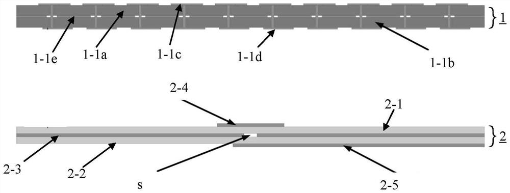
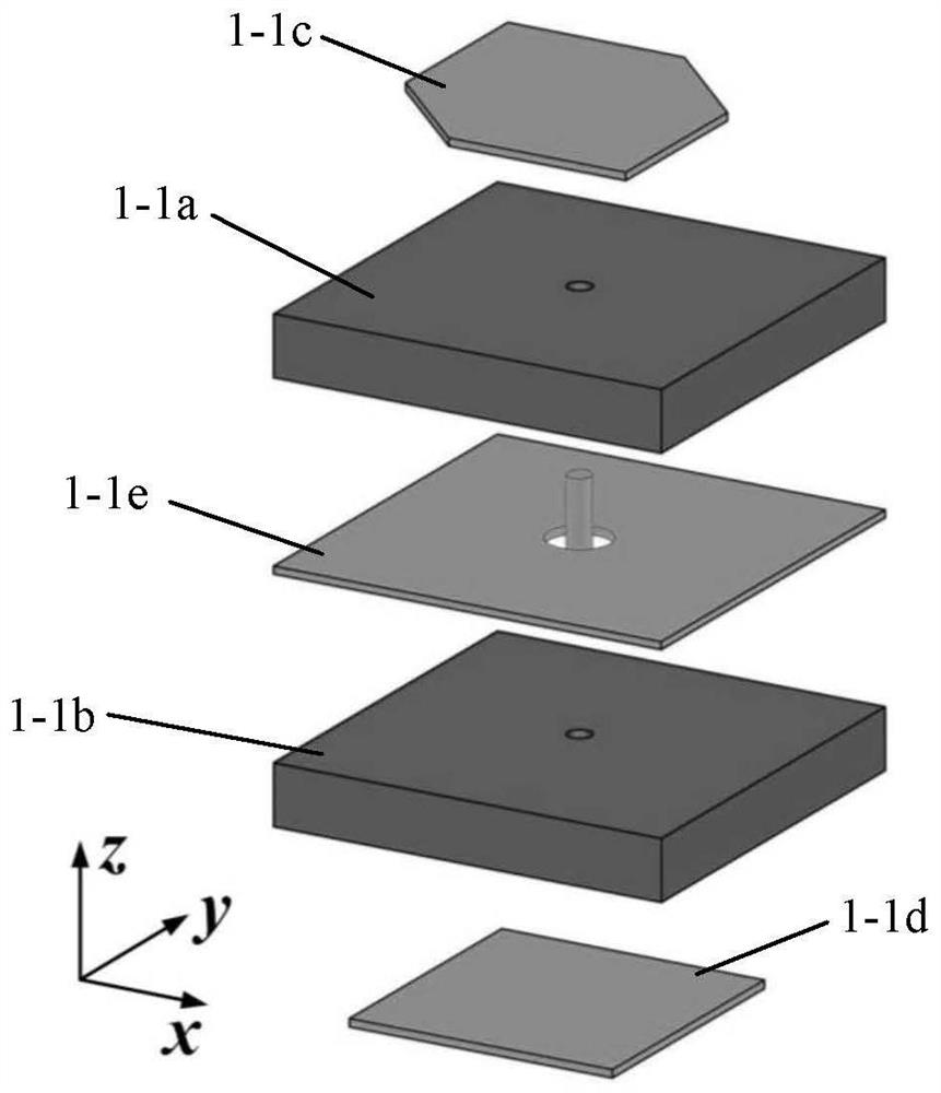
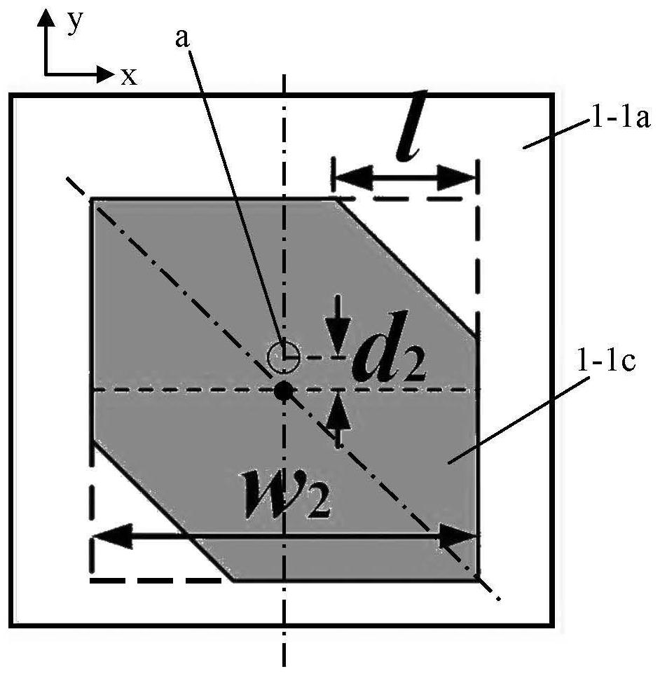
A circularly-polarized FP resonant cavity antenna comprises a linear-circular polarization conversion metasurface, a metasurface unit of the linear-circular polarization conversion metasurface comprises an upper-layer dielectric plate and a lower-layer dielectric plate, a metal floor is arranged between the upper-layer dielectric plate and the lower-layer dielectric plate, a radiation patch is arranged on the upper-layer dielectric plate, the radiation patch is a square with two opposite angles cut off, and the metal floor is arranged between the upper-layer dielectric plate and the lower-layer dielectric plate. The center of a first metalized through hole in the radiation patch coincides with the center of the metasurface unit and does not coincide with the center of the radiation patch, a receiving patch is arranged on the lower layer dielectric plate, and the center of a second metalized through hole in the receiving patch coincides with the center of the metasurface unit and does not coincide with the center of the receiving patch. The metal floor is provided with a through hole, and the centers of the first and second metalized via holes and the through hole coincide; the rotation angle of the radiation patch is 0-360 degrees; the floor is arranged below the linear circular polarization conversion metasurface; and the linear polarization feed source is positioned between the linear circular polarization conversion metasurface and the floor. The antenna provided by the invention can realize beam deflection and circular polarization radiation.

Description

technical field [0001] The invention belongs to the technical field of microwave communication, in particular to a circularly polarized Fabry-Perot resonant cavity antenna. Background technique [0002] Fabry-Perot (FP) resonant cavity antenna is a kind of high gain antenna, which can generate very high gain through a simple structure, so it has been applied in many occasions. Especially with the rise of printed electromagnetic periodic structures, the FP resonator antenna designed as a partially reflective surface (PRS) cladding has the characteristics of simple structure and stable performance, which greatly promotes the FP resonator antenna. It is developing in the direction of easy processing, low profile and low cost. However, most of the current FP resonator antennas radiate linearly, and realizing circularly polarized radiation is the difficulty and the focus of research on FP resonator antennas. Moreover, due to the limitation of its resonant characteristics, the r...

Claims


Application Information

Patent Timeline
Patent Type & Authority Applications(China)
IPC IPC(8): H01Q15/00H01Q15/24H01Q9/04H01Q1/28H01Q1/38H01Q1/50H01Q3/30H01Q19/06H01Q19/10
CPCH01Q15/0026H01Q15/244H01Q9/0428H01Q1/288H01Q1/38H01Q1/50H01Q3/30H01Q19/06H01Q19/10
Inventor 谢鹏赵搏欣赵晓林冯国强
Owner AIR FORCE UNIV PLA
Learn More