Circular cone logarithm helical antenna with frustum

A logarithmic helix and helical line technology, applied in the field of conical logarithmic helix antennas, can solve the problems of easy splitting and low gain, and achieve the effects of improving electromagnetic wave intensity, increasing antenna gain and being convenient to use.

Inactive Publication Date: 2013-10-09
HARBIN INST OF TECH
View PDF2 Cites 3 Cited by
  • Summary
  • Abstract
  • Description
  • Claims
  • Application Information

AI Technical Summary

Problems solved by technology

[0004] The purpose of the present invention is to solve the problem that the existing conical logarithmic helical antenna is easy to split the pattern and the gain is low

Method used


Image

  • Circular cone logarithm helical antenna with frustum

Examples


specific Embodiment approach 1

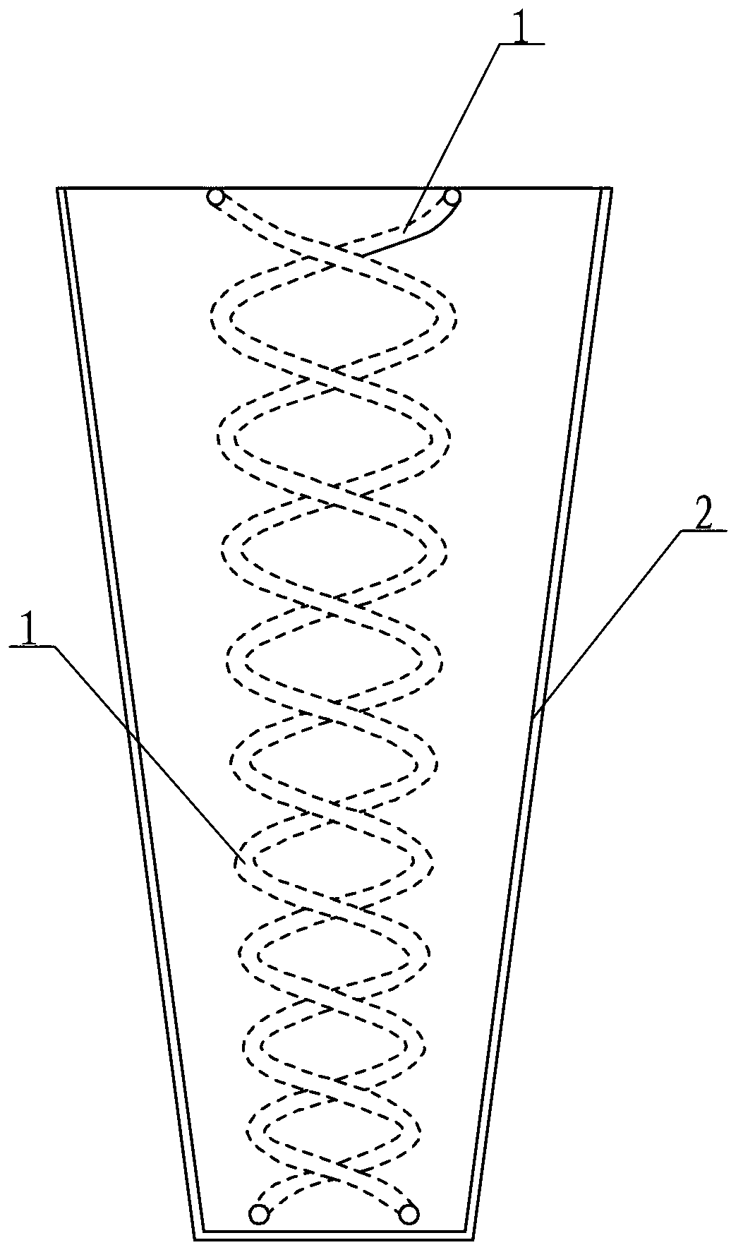
[0016] Specific implementation mode one: combine figure 1 Describe this embodiment, this embodiment includes two one-armed conical logarithmic helical units 1, two one-armed conical logarithmic helical units 1 are rotated 180° along their normals The mathematical expression of ρ=ρ 0 exp bφ,

[0017] in 2θ 0 is the angle between the cone generatrix and the normal line, called the cone opening angle; α is the angle between the conical logarithmic spiral winding direction and the cone generatrix, called the cone inclination angle, φ is the independent variable, that is, the polar coordinate axis and the coordinate axis vertex and the helix The angle formed by each point, ρ is the distance from a point to the vertex of the helix, ρ 0 For the distance between the starting point of the helix and the cone, the conical logarithmic helical antenna also includes a hollow frustum 2, and two single-arm conical logarithmic spiral units 1 are arranged in the hollow frustum 2, 2θ 0 =15...

specific Embodiment approach 2

[0019] Specific implementation mode two: combination figure 1 The present embodiment is described. The radius of the upper bottom surface of the hollow frustum 2 of this embodiment is 20 mm, the radius of the lower bottom surface is 5 mm, and the wall thickness of the hollow frustum 2 is 0.5 mm. With such setting, it is easy to achieve better pattern characteristics and gain characteristics. Other compositions and connections are the same as in the first embodiment.

specific Embodiment approach 3

[0020] Specific implementation mode three: combination figure 1 Describe this embodiment, the lower end surfaces of the two single-arm conical logarithmic screw units 1 of this embodiment are 3 mm away from the center of the inner bottom end of the hollow frustum 2 . With such arrangement, resonance is generated between the antenna and the metal surface, and incident electromagnetic waves and reflected electromagnetic waves can be superimposed on each other, thereby achieving the purpose of increasing the amplitude. Other compositions and connections are the same as those in the second embodiment.


PUM


Abstract

The invention relates to a circular cone logarithm helical antenna, in particular to a circular cone logarithm helical antenna with a frustum. The problems that according to an existing circular cone logarithm helical antenna, a directional diagram is prone to sectioning and gain is low are solved. The circular cone logarithm helical antenna with the frustum comprises two single-arm circular cone logarithm helical units which rotate by 180 degrees along normal lines of the two sing-arm circular cone logarithm helical units and are arranged in a winding mode. The arithmetic expression of the two sing-arm circular cone logarithm helical units (1) is p=p0exp b phi, wherein 2theta0 is the included angle among the circular cone generatrix and the normal lines and called a circular cone opening angle. Alpha is the included angle between the circular cone logarithm helical winding direction and the circular cone genetatrix and called a circular cone inclination angle. Phi is an independent variable and namely the included angle among the top point of a polarization coordinate axis and a coordinate axis and all points of a helical line. The circular cone logarithm helical antenna further comprises the hollow frustum, and the two single-arm circular cone logarithm helical units are arranged in the hollow frustum, wherein 2theta0=15-20 degrees, and alpha=70-80 degrees. The circular cone logarithm helical antenna is used for the fields of mobile phone antennas, wireless local area networks and satellite communications.

Description

technical field [0001] The invention relates to a helical antenna, in particular to a conical logarithmic helical antenna with a truncated cone. Background technique [0002] EMC started earlier in foreign countries. As early as the 1980s, the United States, Germany, Japan and France had reached a very high level in EMC standards and specifications, analysis and prediction, design, measurement and management. The subsequent EMC testing and EMC manufacturing industries are also developing rapidly, and the research and development of EMC test accessories, especially EMC measurement antennas, are becoming more mature and diversified. [0003] With its flat impedance, good circular polarization characteristics, and superior end-fire and side-fire characteristics, the helical antenna has important applications in the field of electromagnetic compatibility testing, and has been widely used in communication, meteorology, and relay fields. The helical antenna is a form of circularl...

Claims


Application Information

Patent Timeline
Patent Type & Authority Applications(China)
IPC IPC(8): H01Q1/36H01Q19/00H01Q19/15
Inventor 邱景辉刘浩祁嘉然王琳月
Owner HARBIN INST OF TECH
Why Eureka
Try Eureka