Broadband miniaturized metasurface antenna based on double-layer capacitive loading

A technology of capacitive loading and metasurface, applied in the direction of antenna, antenna grounding device, radiating element structure, etc., can solve the problems of metasurface antenna array design and integration difficulties, large overall size, size reduction, etc., to achieve cost and Light weight, easy processing, and size reduction effects

Inactive Publication Date: 2020-11-24
SOUTH CHINA UNIV OF TECH
View PDF8 Cites 4 Cited by
  • Summary
  • Abstract
  • Description
  • Claims
  • Application Information

AI Technical Summary

Problems solved by technology

Compared with traditional microstrip patch antennas, metasurface antennas have obvious advantages in performance such as gain and bandwidth, but their overall size is usually larger (~1.1λ0), which leads to There are some difficulties in array design and integration of metasurface antennas
At present, the miniaturization methods of metasurface antennas generally include the following: adopt double-layer / multi-layer structure, load resonant structure (C.Zhao and C.Wang, “Characteristic mode design of wide bandcircularly polarized patch antenna consisting of H-shaped unit cells," IEEE Access, vol.6, pp.25292-25299, 2018.), increasing the current path [7] , reduce the gap between units, and use dielectric plates with high dielectric constants (W.E.I.Liu, Z.N.Chen, X.Qing, J.Shi and F.H.Lin, "Miniaturized wideband metasurface antennas," IEEE Transactions on Antennas and Propagation, vol.65 , no.12, pp.7345-7349, Dec.2017.), etc., but these methods usually have problems such as high profile, narrow bandwidth, and limited size reduction

Method used


Image

  • Broadband miniaturized metasurface antenna based on double-layer capacitive loading
  • Broadband miniaturized metasurface antenna based on double-layer capacitive loading
  • Broadband miniaturized metasurface antenna based on double-layer capacitive loading

Examples


Embodiment Construction

[0045] The present invention will be described in further detail below in conjunction with the embodiments and the accompanying drawings, but the embodiments of the present invention are not limited thereto.

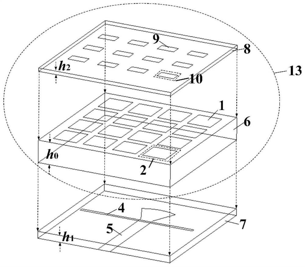
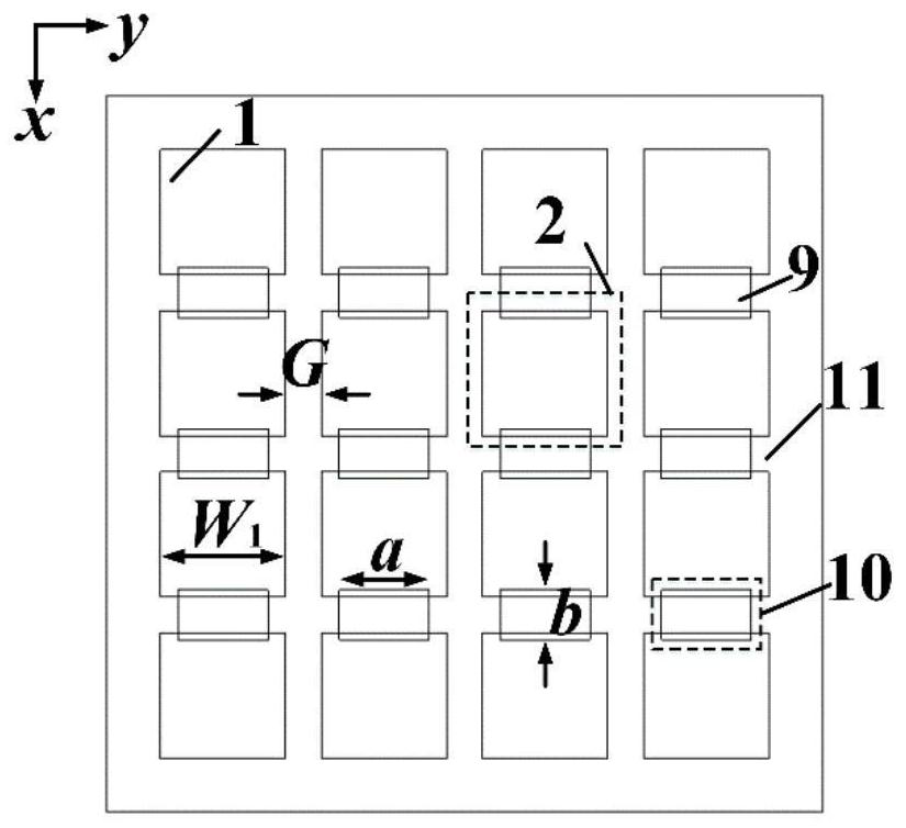
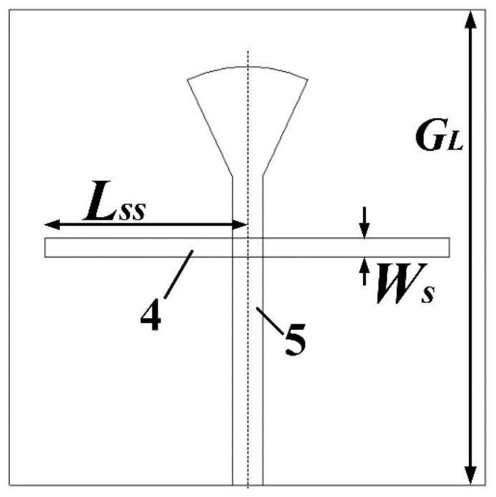
[0046] Such as Figure 1a , Figure 1b , Figure 1c , Figure 1d As shown, a broadband miniaturized metasurface antenna based on double-layer capacitive loading adopts a three-layer stacked dielectric substrate, from top to bottom, including a first layer of dielectric substrate 8, a second layer of dielectric substrate 6 and a third layer of dielectric substrate layer dielectric substrate 7;

[0047] The dielectric constant [2.2,10.2] of the first layer of dielectric substrate 8, the thickness h 2 is [0.001λ 0 ,0.05λ 0 ]; the dielectric constant of the second dielectric substrate 6 is [2.2,10.2], and the thickness h 0 is [0.001λ 0 ,0.1λ 0 ]; the dielectric constant of the third dielectric substrate 7 is [2.2,10.2], and the thickness h 1 is [0.001λ 0 ,0.1λ 0 ]...


PUM

PropertyMeasurementUnit
thicknessaaaaaaaaaa
thicknessaaaaaaaaaa
thicknessaaaaaaaaaa

Abstract

The invention discloses a broadband miniaturized metasurface antenna based on double-layer capacitive loading, which adopts three layers of dielectric substrates which are stacked from top to bottom,and comprises a first layer of dielectric substrate, a second layer of dielectric substrate and a third layer of dielectric substrate, wherein a metal parasitic patch structure for capacitive loadingis printed on the upper surface of the first layer of dielectric substrate, and the metal parasitic patch structure comprises a plurality of parasitic patch units which are periodically arranged; a metasurface radiation structure is printed on the upper surface of the second dielectric substrate, and a metal floor with a coupling gap is printed on the lower surface of the second dielectric substrate; the metasurface structure comprises a plurality of independent metasurface patch units and gaps among the units; the upper surface of the third dielectric substrate is attached to the metal floor,and the lower surface is printed with a feed network. According to the invention, miniaturization is effectively achieved while the broadband characteristic is guaranteed, and the high gain characteristic can still be guaranteed while the size is reduced.

Description

technical field [0001] The invention relates to a metasurface antenna, in particular to a broadband miniaturized metasurface antenna based on double-layer capacitive loading. Background technique [0002] With the development of modern wireless communication systems, the demand for wideband antennas is increasing. Microstrip patch antennas have attracted much attention due to their low profile, light weight, low cost, and easy compatibility with printed circuits. However, the traditional microstrip patch antenna has narrow impedance bandwidth and low gain. Although there are many technologies to overcome this shortcoming, such as using capacitive probe feeding, L probe feeding, aperture coupling, U / E open Groove patch and stack patch, etc., but usually require a thick dielectric substrate with a low dielectric constant, it is difficult to achieve a low profile (D.Chen, W.Yang, W.Che and Q.Xue, "Broadband stable-gain multiresonance antenna using nonperiodic square-ring meta...

Claims


Application Information

Patent Timeline
Patent Type & Authority Applications(China)
IPC IPC(8): H01Q1/38H01Q1/48H01Q15/14
CPCH01Q1/38H01Q1/48H01Q15/14
Inventor 薛泉陈东旭车文荃杨琬琛
Owner SOUTH CHINA UNIV OF TECH
Why Eureka
Try Eureka