Microgrid inverter multi-loop control method based on virtual synchronous generator

A virtual synchronization and control method technology, applied in the direction of single-network parallel feeding arrangement, etc., can solve the problems of lack of scheduling means, inability to take the initiative to system, and large influence on the power grid, so as to simplify the control system, improve the voltage waveform, and improve the power factor. Effect

Active Publication Date: 2016-08-31
SOUTHEAST UNIV
View PDF2 Cites 38 Cited by
  • Summary
  • Abstract
  • Description
  • Claims
  • Application Information

AI Technical Summary

Problems solved by technology

[0003] Due to the random access of such converter-based grid-connected power generation equipment, there are a large number of types, especially in the case of distributed power generation, which lacks scheduling means similar to conventional units, and it cannot actively provide support to the system. Relatively large impact

Method used


Image

  • Microgrid inverter multi-loop control method based on virtual synchronous generator
  • Microgrid inverter multi-loop control method based on virtual synchronous generator
  • Microgrid inverter multi-loop control method based on virtual synchronous generator

Examples


Embodiment Construction

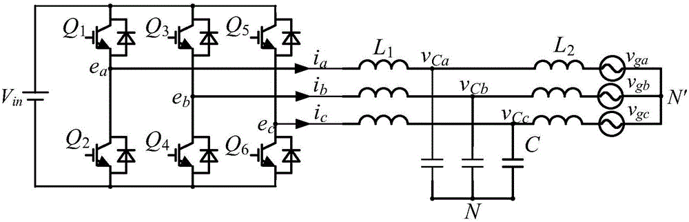
[0022] Such as figure 2 As shown, the figure is a three-phase inverter topology. Among them, V in is the DC voltage on the input side; Q 1 ~Q 6 is the switch tube; e a , e b , e c is the output voltage of the three-phase bridge arm; i a , i b , i c is the three-phase inductor current; L 1 , C and L 2 is the output LCL filter; V Ca , V Cb , V Cc is the three-phase capacitor voltage; V ga , V gb , V gc is the grid voltage.

[0023] go to image 3 , describing the overall control block diagram, which mainly includes a power calculation module, a phase-locked loop module, a coordinate conversion module, a PI regulator, a VSG algorithm module, a voltage and current double closed-loop module and a PWM modulation module.

[0024] First, the voltage and current sensors detect the three-phase capacitor voltage on the output side and the current u on the inductor inv,a,b,c , i La,b,c . The detected output side voltage and current are used in two modules, one is a p...


PUM


Abstract

The invention discloses a microgrid inverter multi-loop control method based on a virtual synchronous generator, and the method comprises power control of an outer loop and voltage current control of an inner loop. The power control of the outer loop comprises the following steps: measuring the three-phase voltage and current of an output side of an inverter, calculating active power and reactive power according to the instantaneous power theory, carrying out calculation and regulation through an active power-frequency equation, a reactive frequency equation, a torque inertia equation and an electromagnetic transient equation of a synchronous motor, obtaining the amplitude of an output voltage and a phase angle given value, and then carrying out modulation through voltage and current double loops. The method can achieve the non-corresponding control of voltage size and frequency well, outputs active and reactive power, can achieve precise manual control, and has the characteristics of V/F and PQ control. When a fault happens to a power grid, the method can simulate the primary modulation, primary voltage regulation and inertia characteristics of the synchronous generator, participates in the power grid adjustment, provides frequency and voltage support, and facilitates the stabilization of the power grid.

Description

technical field [0001] The invention relates to a control technology of a micro-grid inverter, in particular to a multi-loop control method of a micro-grid inverter based on a virtual synchronous generator. Background technique [0002] With the popularity of new energy sources, the proportion of traditional generator power generation in energy is gradually decreasing. The current power system is based on parallel networking of synchronous generator voltage sources, and adopts centralized dispatching and management operation; at present, almost mainstream new energy commercial grid-connected converters regard the grid as the master, itself as the slave, and control itself as the current source way to connect to the grid. [0003] Due to the random access of such converter-based grid-connected power generation equipment, there are a large number of types, especially in the case of distributed power generation, which lacks scheduling means similar to conventional units, and i...

Claims


Application Information

Patent Timeline
Patent Type & Authority Applications(China)
IPC IPC(8): H02J3/38H02J3/48
CPCH02J3/38H02J3/48
Inventor 王建华顾彬仕季振东
Owner SOUTHEAST UNIV
Why Eureka
Try Eureka