
Repeater for automatically adjusting position, repeater system and relay method

An automatic adjustment, repeater technology, applied in the direction of transmission system, radio transmission system, electrical components, etc., can solve the problem of wireless repeater limitation, inability to move, unable to move by wifi users, etc.

Active Publication Date: 2016-08-31
MIDEA GRP CO LTD
View PDF6 Cites 18 Cited by
  • Summary
  • Abstract
  • Description
  • Claims
  • Application Information

AI Technical Summary

Problems solved by technology

However, the existing repeaters need to be fixed at a fixed position, such as the wall plug power used by TP-Link wifi wireless repeater and Tenda wifi wireless repeater. It needs to be fixed in one position and cannot be moved due to the limitation of the wall, and it needs to monopolize a wall power supply, which wastes the socket resources of the household power supply
Another example is the Xiaomi wifi wireless repeater, which is designed with a USB port, so it is also limited by the position of the USB port and needs to be fixed in one position and cannot be moved.
In short, the position of the existing wireless repeater is greatly restricted and cannot be moved according to the needs of wifi users, so it cannot provide high-quality network signals for wifi users according to the location of wifi users
At the same time, because the wireless repeater is fixed at a specific location and cannot be moved, some families need to set up multiple wireless repeaters to cover all indoor users, which increases the cost of wifi usage.

Method used


Image

  • Repeater for automatically adjusting position, repeater system and relay method
  • Repeater for automatically adjusting position, repeater system and relay method
  • Repeater for automatically adjusting position, repeater system and relay method

Examples


Embodiment Construction

[0033] The present invention will be described in further detail below in conjunction with the accompanying drawings and embodiments. The following examples are used to illustrate the present invention, but should not be used to limit the scope of the present invention.

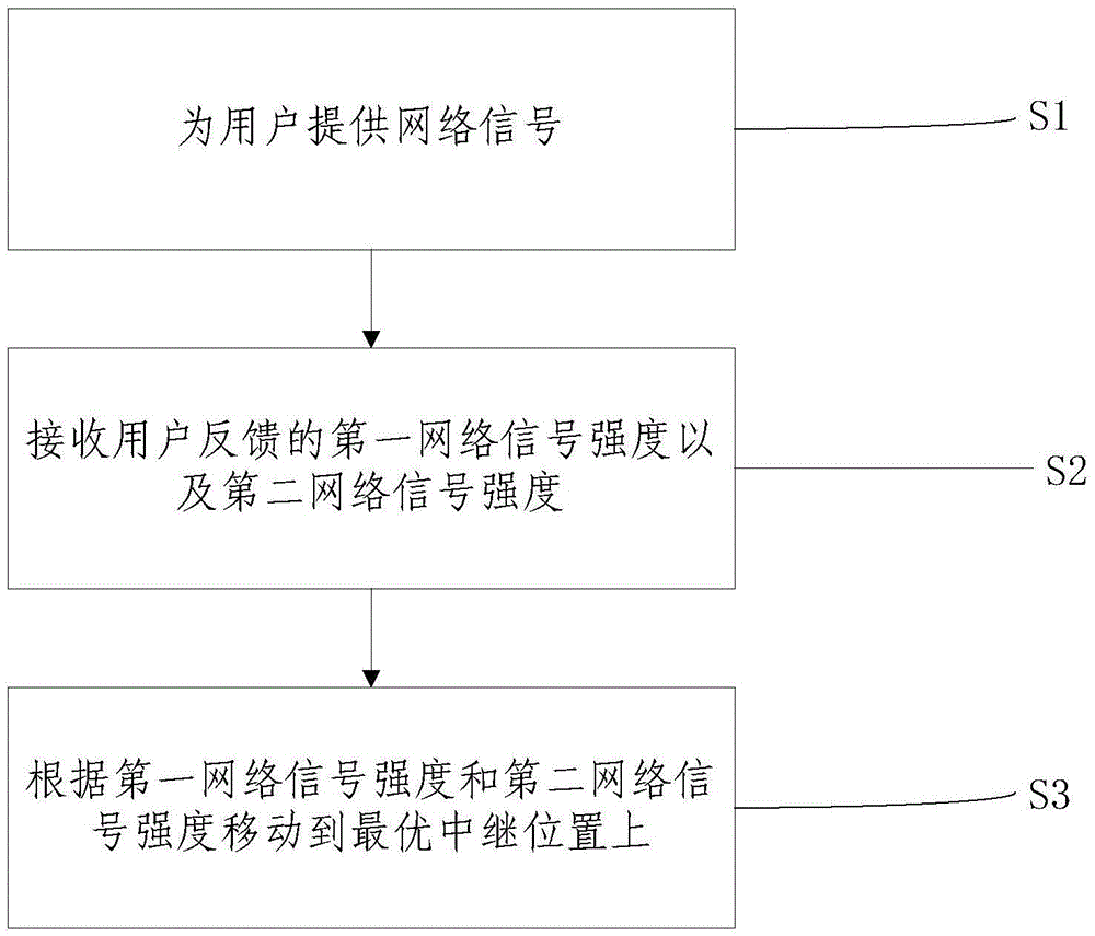
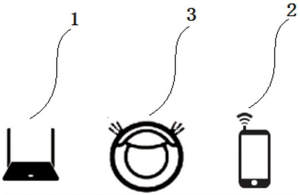
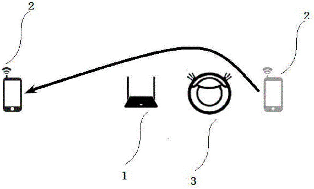
[0034] In order to solve the technical problems of the inability of the repeater to move and the poor quality of the network signal received by the user and the high cost of wifi usage due to the inability of the repeater to be moved, the present invention provides a repeater that automatically adjusts its position , the repeater includes an automatic moving device and a repeater body fixed on the automatic moving device. The repeater body provides network signals for the user, and at the same time receives the first network signal strength and the second network signal strength fed back by the user, and sends the first network signal strength and the second network signal strength to the automatic mobile dev...


PUM


Abstract

The invention discloses a repeater for automatically adjusting a position, a repeater system and a relay method. A repeater body is fixed on an automatic mobile apparatus, the repeater body is utilized for providing network signals for a user, receiving first network signal intensity and second network signal intensity fed back by the user at the same time, and sending the first network signal intensity and the second network signal intensity to the automatic mobile apparatus; and the automatic mobile apparatus, according to the first network signal intensity and the second network signal intensity, moves to an optimal relay position, i.e., the repeater body moves to the optimal relay position along with the automatic mobile apparatus, at the moment, the intensity of the network signals which are received by the user and provided by the repeater body is the maximum, and the network signal intensity is smaller than the second network signal intensity. According to the invention, the repeater can move according to the position of the user, high-intensity network signals are provided for users located at any positions, arrangement of multiple repeaters can be avoided, and the application cost of wifi is decreased.

Description

technical field [0001] The present invention relates to the field of smart home appliances, and more particularly to a repeater for automatically adjusting a position, a repeater system and a repeater method. Background technique [0002] With the popularity of the Internet of Things, wifi has become the preferred way for the Internet of Things home appliances to connect. However, due to the limited coverage and penetration of wifi, it cannot meet the networking needs of some home appliances in the Internet of things, especially some household appliances in the corner cannot be connected to wifi, so that remote control cannot be realized. [0003] Therefore, some families use wifi wireless repeaters to expand wifi coverage. There are many kinds of wireless repeaters commonly used now, such as TP-Link, Tenda, Xiaomi and other wifi wireless repeaters. However, the existing repeaters need to be fixed at a fixed position, such as the wall plug power used by TP-Link wifi wirele...

Claims


Application Information

Patent Timeline
IPC IPC(8): H04B7/155
CPCH04B7/15507
Inventor 周子航
Owner MIDEA GRP CO LTD
Learn More