Electrical energy storage device having balance-imbalance converter

A balancing converter and storage device technology, applied in circuit devices, battery circuit devices, charge equalization circuits, etc., can solve problems such as expensive plug systems

Active Publication Date: 2016-08-31
LIEBHERR COMPONENTS BIBERACH GMBH
View PDF9 Cites 0 Cited by
  • Summary
  • Abstract
  • Description
  • Claims
  • Application Information

AI Technical Summary

Problems solved by technology

At the same time, the cables from the balun to the tap of the storage block also require a larger cross-section
Plug systems get more expensive

Method used


Image

  • Electrical energy storage device having balance-imbalance converter

Examples


Embodiment Construction

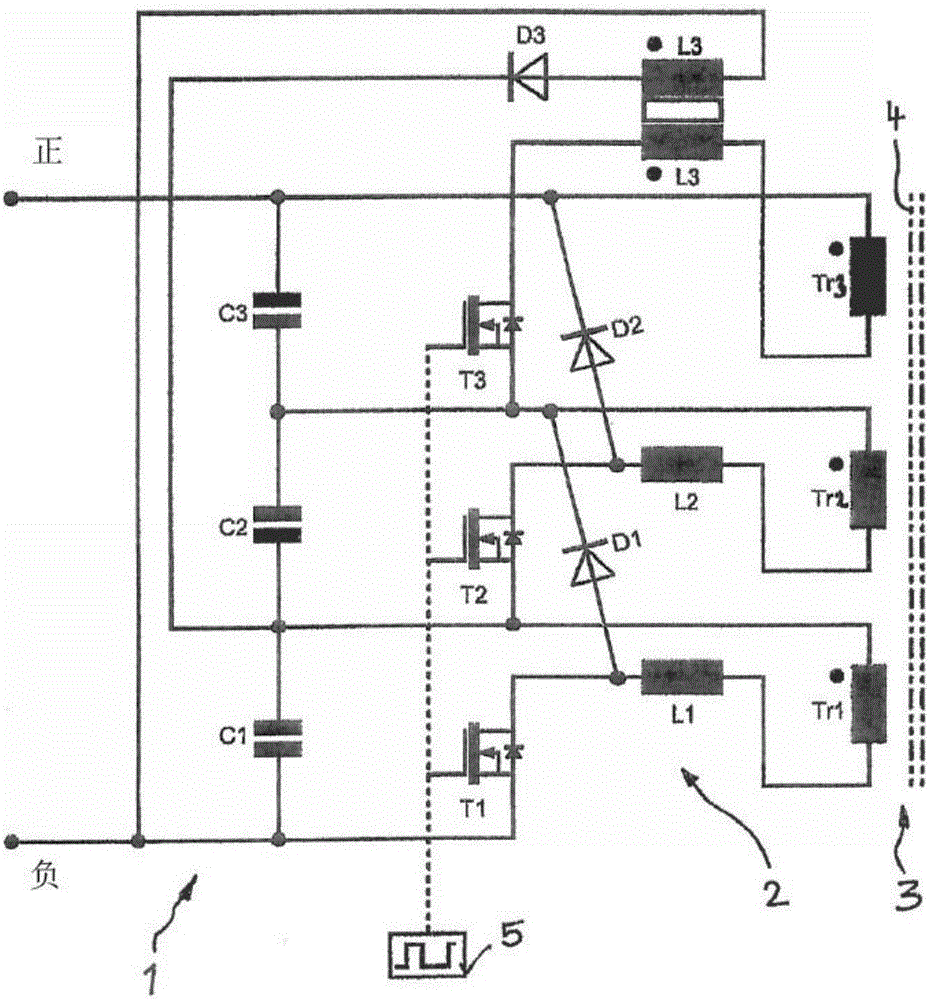
[0036] Such as figure 1 As shown, the energy storage 1 or energy storage module may comprise a plurality of accumulators C1 , C2 and C3 which are connected in series or in series and which are connected to a common negative pole and a common positive pole of the energy storage 1 . In this respect, the accumulator C1 is directly connected to the negative pole, while the accumulator C3 is arranged closest to the positive pole of the energy store 1 .

[0037] even though figure 1 Only three accumulators C1 , C2 , C3 are shown, it being understood that the energy storage 1 may comprise any desired number (in particular a plurality) of accumulators C1 . . . Cn connected in series with each other.

[0038] Such as figure 1 As shown, the balun 2 is associated with the batteries C1, C2 and C3 connected in series, and includes a balancing transformer 3 that is common to all the batteries and includes a number of active currents corresponding to the number of batteries. Separated coi...


PUM


Abstract

The present invention relates to an electrical energy storage unit (1) comprising a plurality of series-connected electrical storage cells (C1, C2, C3) and an inductive balance-imbalance converter (2) for balancing the storage cell voltages, wherein the balance-imbalance converter has a balancing transformer (3) having separate individual windings (Tr1, Tr2, Tr3) for the storage cells as well as in each case an electrical switch (T1, T2, T3) for each storage cell. The windings of the balancing transformer are in each case connected to a pole of the respective storage cell by means of at least one inductance (L1, L2, L3) and a switch connected to the inductance, wherein the switch associated with a respective storage cell is connected by means of a diode (D1, D2, D3) to a pole of a respective storage cell disposed upstream or downstream.

Description

technical field [0001] The present invention relates to an electrical energy storage device having a plurality of accumulators connected in series, and to an inductive balun for balancing the voltage of the accumulators, wherein the balun has multiple functions for the accumulators separate single-coil balancing transformers with corresponding electrical switches for each battery. Background technique [0002] In order to be able to efficiently operate electrical machines with highly variable and periodic power consumption, it is necessary to provide energy storage that can store large amounts of energy and that can receive and output them within a short period of time. Such requirements are imposed, for example, on self-propelled work machines including electric traction drives, such as mobile construction machines, but also on land installations, which sometimes cannot be connected to the public grid due to highly variable power consumption , and requires its own generato...

Claims


Application Information

Patent Timeline
Patent Type & Authority Applications(China)
IPC IPC(8): H02J15/00H02J7/00
CPCH02J7/00H02J15/00H02J7/0016H02J7/345H02J7/0019
Inventor 沃尔夫冈·舒斯特斯文·韦尔瑟
Owner LIEBHERR COMPONENTS BIBERACH GMBH
Why Eureka
Try Eureka