Al technical title is built by PatSnap Al team. It summarizes the technical point description of the patent document.
A clamp, integrated technology, used in auxiliary devices, auxiliary welding equipment, welding/cutting auxiliary equipment, etc., can solve the problems of limited clamping output torque of eccentric clamping cylinder, inability to achieve self-locking, and long order cycle. , to achieve the effect of fast adjustment, convenient on-site adjustment, stable and reliable performance
Inactive Publication Date: 2016-09-07
TIANJIN FUZHEN IND EQUIP
View PDF5 Cites 0 Cited by
Summary
Abstract
Description
Claims
Application Information
AI Technical Summary
This helps you quickly interpret patents by identifying the three key elements:
Problems solved by technology
Method used
Benefits of technology
Problems solved by technology
[0003] One is the use of eccentric clamping cylinder, the clamping output torque of eccentric clamping cylinder is limited, and self-locking cannot be realized
[0004] The second is to purchase an integrated clamping cylinder. The common integrated clamping cylinder on the market has the following common problems: that is, it is inconvenient to adjust, and additional adjustment bolts must be purchased when the opening angle of the cylinder needs to be adjusted; it is often necessary to order from abroad, and the order cycle long and very expensive
Method used
Image
Click on the blue label to locate the original text in one second.
Reading with bidirectional positioning of images and text.
Examples
Embodiment Construction
[0021] Below in conjunction with the accompanying drawings and preferred embodiments, the specific implementation, structure and features provided by the present invention are described in detail as follows:
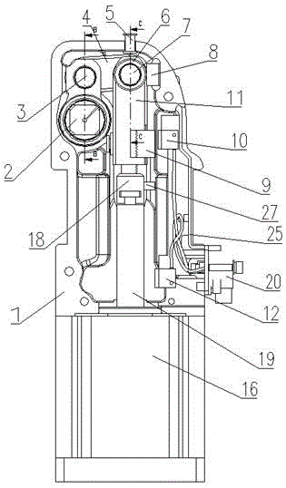
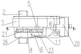
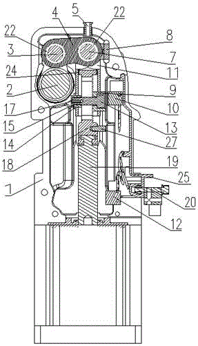
[0022] Such as Figure 1-Figure 5 As shown, an integrated clamp includes a housing 1, a clamping arm rotating part 2, a rotating shaft 3, a connecting rod 4, an auxiliary pin 5, a bearing 6, a rotating shaft 7, and reinforcement Block 8, adjusting stop block 9, clamping in place proximity switch 10, active rod 11, opening in place proximity switch 12, locking bolt 13, T-shaped nut 14, anti-off block 15, cylinder 16, anti-off block fixing bolt 17 , adjusting plate 18, cylinder piston rod 19, proximity switch external connector 20, jackscrew one 21, axle sleeve 22, jackscrew two 23, damping ring 24, proximity switch support 25, bearing two 26 and open inductive block 27 in place.
[0023] The housing 1 is equipped with a cylinder 16, the clamping arm rotating part 2 is in...
PUM
Abstract
The invention relates to an integrated clamping device. The clamping device comprises a housing, a clamping arm rotating part, a first rotating shaft, a connecting rod, an assisting pin, a first bearing, a second rotating shaft, a reinforced block, an adjusting locking block, a clamping-in-place proximity switch, a driving rod, an opening-in-place proximity switch, a locking bolt, a T-shaped nut, a separating preventing block, a cylinder, a separating preventing block fixing bolt, an adjusting plate, a cylinder piston rod and a proximity switch bracket, wherein the proximity switch bracket is connected to the housing; the clamping arm rotating part, the connecting rod and the driving rod form a connecting rod mechanism; when the locking bolt is released, teeth between the adjusting locking block and the adjusting plate are separated, so that the mounting length between the adjusting plate and the driving rod can be varied, and as a result, an opening angle of the clamping arm rotating part can be adjusted. According to the integrated clamping device, small working air pressure can be utilized to generate large clamping force which enables automatic locking in a clamping position, so that the safety and reliability in use can be ensured; a standard modular structure is adopted, and an output torque value is fixed, so that the clamp design and model selection can be conveniently carried out; automatic control can be achieved; in addition, field adjusting can be conveniently carried out.
Description
technical field [0001] The invention relates to a kind of automobile manufacturing equipment, in particular to an integrated clamper used for the welding of automobile bodies. Background technique [0002] At present, the production competition in the automobile industry is very fierce. There are usually two clamping methods in the field of automobile manufacturing equipment: [0003] One is the use of eccentric clamping cylinder, which has limited clamping output torque and cannot realize self-locking. [0004] The second is to purchase an integrated clamping cylinder. The common integrated clamping cylinder on the market has the following common problems: that is, it is inconvenient to adjust, and additional adjustment bolts must be purchased when the opening angle of the cylinder needs to be adjusted; it is often necessary to order from abroad, and the order cycle long and very expensive. [0005] Therefore, to provide an integrated clamp with simple structure, reasonab...
Claims
Application Information
Patent Timeline
Application Date:The date an application was filed.
Publication Date:The date a patent or application was officially published.
First Publication Date:The earliest publication date of a patent with the same application number.
Issue Date:Publication date of the patent grant document.
PCT Entry Date:The Entry date of PCT National Phase.
Estimated Expiry Date:The statutory expiry date of a patent right according to the Patent Law, and it is the longest term of protection that the patent right can achieve without the termination of the patent right due to other reasons(Term extension factor has been taken into account ).
Invalid Date:Actual expiry date is based on effective date or publication date of legal transaction data of invalid patent.