Disassembling clamping apparatus for valve core of steam intake valve

A spool and valve technology, which is applied in hand-held tools, manufacturing tools, workpiece clamping devices, etc., can solve problems such as difficult disassembly and spool lock, so as to save fixture costs, improve service life and life, and improve The effect of maintenance efficiency

Active Publication Date: 2016-09-07
DATANG NANJING POWER PLANT
View PDF9 Cites 0 Cited by
  • Summary
  • Abstract
  • Description
  • Claims
  • Application Information

AI Technical Summary

Problems solved by technology

The invention solves the problem that the spool of the steam inlet valve is locked and difficult to disassemble after the spool of the steam inlet valve is damaged, improves the maintenance efficiency of the valve, and reduces the replacement and maintenance cost of the steam inlet valve. In addition, the dismantling fixture of the invention has a simple structure and is easy to manufacture , the vulnerable parts can be replaced, the production cost is low, and it is conducive to popularization

Method used


Image

  • Disassembling clamping apparatus for valve core of steam intake valve
  • Disassembling clamping apparatus for valve core of steam intake valve
  • Disassembling clamping apparatus for valve core of steam intake valve

Examples


Embodiment approach 1

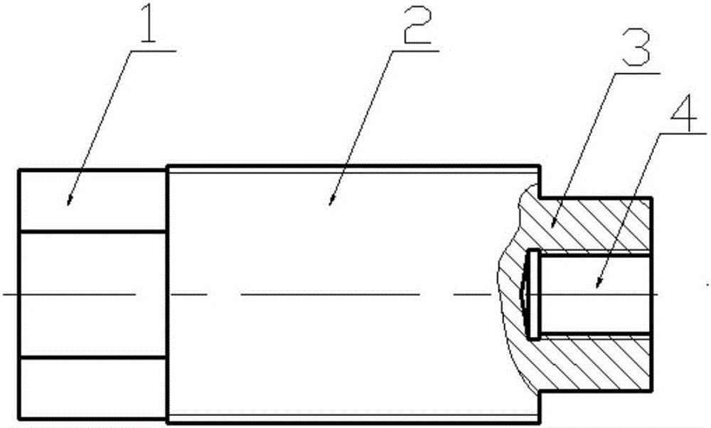
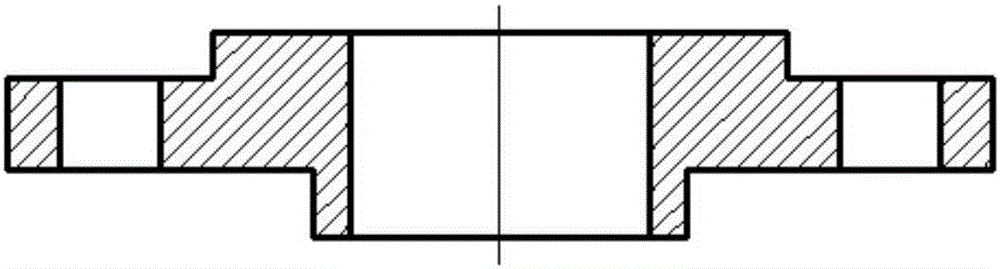
[0040] Please refer to the attached Figure 2-6 , the embodiment of the present invention provides a professional dismantling fixture for dismantling the steam inlet valve that cannot be repaired due to the locked valve core, including a central rod ( figure 2 ), fixed flange ( image 3 ) and spool wrench ( Figure 4 with Figure 5 ).

[0041] center pole ( figure 2 ) includes a head structure 1, a central screw 2 and a tail structure 3. The outer circumference of the head structure 1 is a hexagonal structure with a diagonal length of 67mm, which is fixedly connected with the central screw 2, which is convenient to use a percussion wrench to drive the entire central rod to rotate. The tail structure 3 is also fixedly connected with the central screw 2, and the outer circumference of the tail structure 3 is a hexagonal structure with a diagonal length of 52mm.

[0042] The outer wall of central screw rod 2 has threads, and the fixed flange ( image 3 ) inner wall also h...

Embodiment approach 2

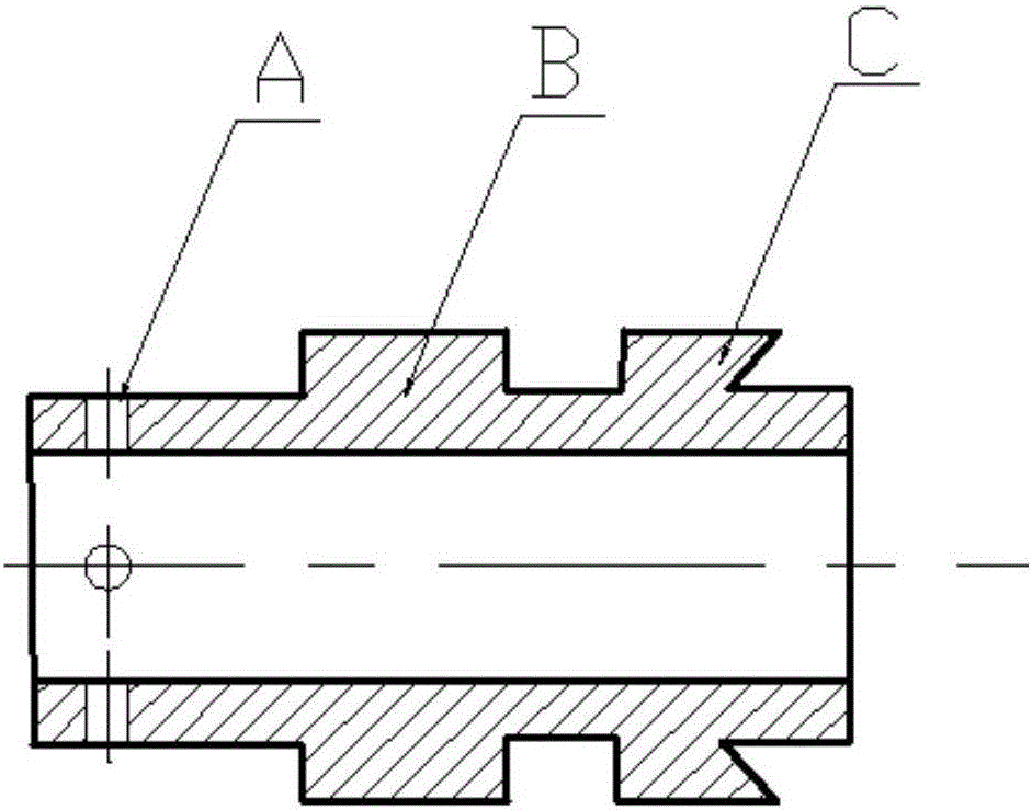
[0054] The difference between this embodiment and Embodiment 1 is that the central rod ( figure 1 ) The outer periphery of the tail structure 3 is a stepped structure, the spool wrench ( Figure 4 with Figure 5 ) is a stepped structure matching the tail structure, the spool wrench is sleeved on the tail structure 3, the stepped structure limits the axial movement of the spool wrench, and other structures, installation methods and working processes are the same.

Embodiment approach 3

[0056] The difference between this embodiment and Embodiment 1 is that the central rod ( figure 1 The outer circumference of the tail structure 3 of ) is circular, the outer wall is provided with external threads opposite to the thread direction of the central screw rod 2, and the inner wall of the center through hole of the valve core wrench is provided with internal threads matching the outer wall threads of the tail structure. The spool wrench is connected with the tail structure of the center rod by threads. This embodiment does not need fixing parts, and the center of the tail structure does not need to be provided with an installation hole, and other structures, installation methods, and working processes are the same as Embodiment 1.

[0057] From the above it can be seen that:

[0058] (1) The dismantling fixture of the present invention can fix the fixture on the steam inlet valve through the fixing flange. Since the center rod and the fixing flange are connected by ...


PUM


Abstract

The invention discloses a disassembling clamping apparatus for a valve core of a steam intake valve. The disassembling clamping apparatus comprises a center rod, a fixed flange and a valve core spanner, wherein the center rod comprises a head structure, a center screw rod and a tail structure; the head structure and the tail structure are separately positioned at two ends of the center screw rod; the center screw rod is in thread connection to the fixed flange; the head structure and the tail structure are separately positioned on two sides of the fixed flange; the fixed flange is detachably connected with the steam intake valve; the valve core spanner is detachably fixed on the tail structure of the center rod. The disassembling clamping apparatus disclosed by the invention solves the difficult problem that after the valve core of the steam intake valve is damaged, the valve core is locked up and is not liable to disassemble; the maintenance efficiency of the valve is improved; the replacement and maintenance cost of the steam intake valve is reduced. In addition, the disassembling clamping apparatus disclosed by the invention is simple in structure, convenient to manufacture, and low in manufacturing cost, and components which are easy to damage can be replaced.

Description

technical field [0001] The invention belongs to the field of equipment fixing and dismantling devices, and in particular relates to a dismantling jig for a valve core of a steam inlet valve. Background technique [0002] The steam inlet valve of the soot blower on the boiler is the only device on the soot blower to control high-temperature steam. The high working temperature and frequent use are prone to damage to the valve core, resulting in steam leakage from the steam inlet valve and excessive noise during operation. For this reason, the steam inlet valve is often replaced, resulting in a large number of damaged valves. The original valve manufacturer provides valve spool disassembly fixtures to facilitate maintenance personnel to repair the valve. In actual use, it is found that when the valve core is disassembled, because the valve is in a high-temperature working environment for a long time, the connection between the valve core and the valve body is often locked, whi...

Claims


Application Information

Patent Timeline
Patent Type & Authority Applications(China)
IPC IPC(8): B25B11/02B25B27/24
CPCB25B11/02B25B27/24
Inventor 徐万顺孙澄周子俊何卫国
Owner DATANG NANJING POWER PLANT
Why Eureka
Try Eureka