Device for achieving cable logging based on excavator
A timber skidding and cableway technology, which is applied to cranes, transportation and packaging, and cable cranes, etc., can solve problems such as high labor intensity, low utilization rate, and outdated methods, so as to improve operation safety, improve timber skidding efficiency, and reduce operating costs. cost effect
- Summary
- Abstract
- Description
- Claims
- Application Information
AI Technical Summary
Problems solved by technology
Method used
Image
Examples
specific Embodiment approach 1
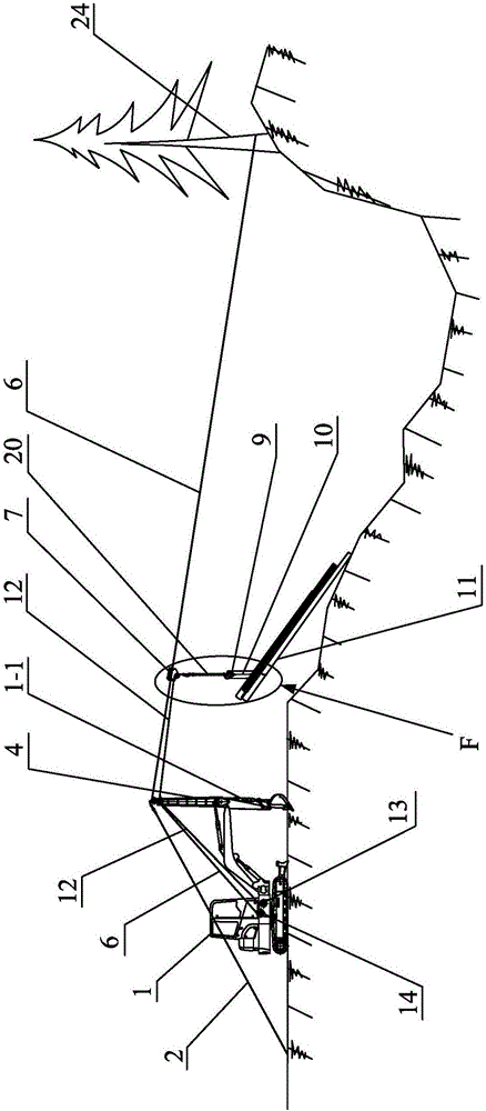
[0035] Specific implementation mode one: combine Figure 1 to Figure 6 , Figure 9 to Figure 14 Describe this embodiment, a cableway material-collecting device based on an excavator in this embodiment includes an excavator 1, a cable-stayed fixed cable 2, a steel support frame rod 4, a first pulley block, a second pulley block, a load-bearing cable 6, and a remote control sports car 7. Load-bearing cable 12, load-bearing cable winch machine 13, load-bearing cable winch machine 14, chain 20, multiple lock collars 9, multiple bundled wooden cables 10, multiple three-way quick locks 21 and multiple wire rope joints 30 ;
[0036]The auxiliary arm 1-1 of the excavator 1 is in a state of being vertical to the ground, the steel support frame rod 4 is perpendicular to the ground, the lower end of the steel support frame rod 4 is hinged on the upper end of the auxiliary arm 1-1 of the excavator 1, and the cable-stayed fixed cable 2 is arranged obliquely One end of the cable-stayed fi...
specific Embodiment approach 2
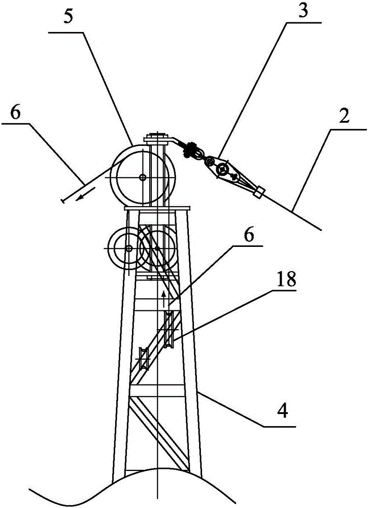
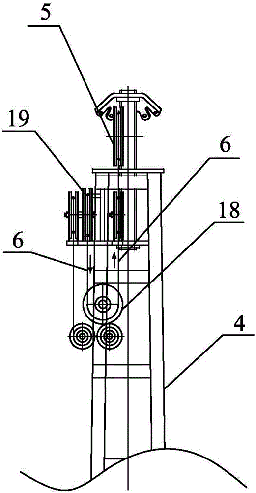
[0042] Specific implementation mode two: combination figure 2 and image 3 Describe this embodiment, the first pulley block of this embodiment comprises the first fixed pulley 5, the second fixed pulley 19 and the third fixed pulley 18, the first fixed pulley 5, the second fixed pulley 19 and the third fixed pulley 18 are formed by the upper Arranged successively from the bottom to the steel support frame bar 4, the axis of the first fixed pulley 5 is parallel to the axis of the second fixed pulley 19, and the axis of the third fixed pulley 18 is perpendicular to the axis of the second fixed pulley 19. The other end of the bearing cable 6 bypasses the second fixed pulley 19 from the top, the third fixed pulley 18 from the bottom, and the first fixed pulley 5 from the top, and then fixes it at the foot of the mountain opposite the excavator 1. The trunk bottom of the living standing tree 24. The winding direction of the bearing cable 6 is as follows: figure 2 and image 3...
specific Embodiment approach 3
[0043] Specific implementation mode three: combination Figure 4 and Figure 5 Describe this embodiment, the second pulley block of this embodiment includes the fourth fixed pulley 25, the fifth fixed pulley 27 and two sixth fixed pulleys 26, the fourth fixed pulley 25, the fifth fixed pulley 27 and two sixth fixed pulleys. The pulleys 26 are respectively rotatably connected with the steel support frame rod 4, the fourth fixed pulley 25, the fifth fixed pulley 27 and the second fixed pulley 19 are located at the same height and the axes of the three are parallel, and the two sixth fixed pulleys 26 are arranged side by side on the second fixed pulley. Below the four fixed pulleys 25, the axes of the two sixth fixed pulleys 26 are all perpendicular to the fourth fixed pulley 25, and the other end of the load-bearing cable 12 bypasses the fourth fixed pulley 25 from above, and then turns downward from below. Cross two the 6th fixed pulleys 26, walk around the 5th fixed pulley 27...
PUM
 Abstract
Description
Claims
Application Information
 - R&D
- Intellectual Property
- Life Sciences
- Materials
- Tech Scout
- Unparalleled Data Quality
- Higher Quality Content
- 60% Fewer Hallucinations
Browse by: Latest US Patents, China's latest patents, Technical Efficacy Thesaurus, Application Domain, Technology Topic, Popular Technical Reports.
© 2025 PatSnap. All rights reserved.Legal|Privacy policy|Modern Slavery Act Transparency Statement|Sitemap|About US| Contact US: help@patsnap.com


