Gear selecting and shifting hydraulic soft shaft

A shift selection, hydraulic technology, applied in the direction of components with teeth, belts/chains/gears, mechanical equipment, etc., can solve the problem that the shift selection flexible shaft cannot transmit the driver's operation intention 100%, affecting the shifting accuracy. , comfort, affecting the shifting feel and other issues, to achieve the effect of improving the shifting feel, improving the shifting comfort, and having a good sealing effect

Inactive Publication Date: 2016-09-07
合肥创智汽车技术开发有限公司
View PDF4 Cites 1 Cited by
  • Summary
  • Abstract
  • Description
  • Claims
  • Application Information

AI Technical Summary

Problems solved by technology

The existence of empty travel makes it impossible for the flexible shaft to transmit the driver's operation intention 100%, resulting in a decrease in stroke efficiency, which causes a series of problems, including: affecting the shifting feel, affecting the accuracy and comfort of shifting

Method used


Image

  • Gear selecting and shifting hydraulic soft shaft
  • Gear selecting and shifting hydraulic soft shaft

Examples


Embodiment

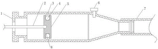
[0016] refer to Figure 1-2 , a hydraulic flexible shaft for shifting gears, including a hydraulic cylinder housing 1, a push rod 2 is provided on one side of the hydraulic cylinder housing 1, and one end of the push rod 2 extends into the hydraulic cylinder housing 1, and a piston is arranged in the hydraulic cylinder housing 1 5. The piston 5 is connected with the push rod 2. There is a groove 8 in the middle of the piston 5. A first seal ring 4 is arranged between the inner walls of the groove 8. The side of the first seal ring 4 away from the piston 5 is provided with a second seal. The other side of the ring 3 and the hydraulic cylinder housing 1 is connected with a shaft body 7 , and the side of the hydraulic cylinder housing 1 close to the shaft body 7 is provided with an air release screw 6 . The beneficial effects of the present invention are: reasonable design, easy to use, the gas in the hydraulic pipeline can be drawn out through the vent screw hole by using the ve...

example 1

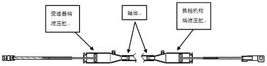
[0018] Example 1: There are two hydraulic cylinder housings 1, one is the hydraulic cylinder at the transmission end, and the other is the hydraulic cylinder at the shift mechanism end. A shaft body 7 is connected between the hydraulic cylinder at the transmission end and the hydraulic cylinder at the shift mechanism end. and the shift mechanism end joints are traditional automobile gear selection flexible shafts, wherein the transmission end joint and the shift mechanism end joint are connected with the transmission end hydraulic cylinder and the shift mechanism end hydraulic cylinder through the push rod 2 respectively. The air screw 6 can extract the gas in the hydraulic pipeline through the exhaust screw hole, and prevent the liquid from overflowing through the screw seal, and has the function of supplementing the liquid; the first seal ring 4 and the second seal ring 3 cooperate to have It has the characteristics of low starting resistance, good sealing effect, small slidi...


PUM


Abstract

The invention discloses a gear selecting and shifting hydraulic soft shaft. The gear selecting and shifting hydraulic soft shaft comprises a hydraulic cylinder shell. A push rod is arranged on one side of the hydraulic cylinder shell. One end of the push rod extends into the hydraulic cylinder shell. A piston is arranged in the hydraulic cylinder shell and connected with the push rod. A groove is formed in the middle portion of the piston. A first seal ring is arranged between inner walls of the groove. A second seal ring is arranged on the side, away from the piston, of the first seal ring. The other side of the hydraulic cylinder shell is connected with a shaft body. A gas bleed screw is arranged on the side, close to the shaft body, on the hydraulic cylinder shell. The gear selecting and shifting hydraulic soft shaft is reasonable in design, gas in hydraulic pipelines can be drawn out through a gas bleed screw hole, and liquid is prevented from flowing out; the gear selecting and shifting hydraulic soft shaft has the beneficial effects of being low in start resistance, good in sealing effect, small in sliding resistance, high in movement speed and the like; and the idle stroke generated by the size interval between steel wire structures frequently used at present is eliminated, and therefore the stroke efficiency is improved, the gear shifting hand feeling is improved, and the gear shifting comfort is improved.

Description

technical field [0001] The invention relates to the technical field of automobile equipment, in particular to a hydraulic flexible shaft for selecting and shifting gears. Background technique [0002] The shifting flexible shaft is the connecting part of the car used to connect the manual or automatic transmission and the shift handle mechanism. It is mainly responsible for transmitting the force and motion displacement applied by the driver on the shift handle mechanism to the execution of the transmission. Mechanism, which controls the transmission to switch gears; the existing flexible shafts for shifting are steel wires (core wires) plus sheaths (flexible shaft sheaths), and the force and motion displacement exerted by the above-mentioned driver are transmitted through the push and pull of the core wires; In such a mechanism, since the core wire must pass through the sheath, there is inevitably a gap between the core wire and the sheath. With the length of the flexible ...

Claims


Application Information

Patent Timeline
Patent Type & Authority Applications(China)
IPC IPC(8): F16H59/02
CPCF16H59/02F16H2306/00
Inventor 吴兴泉樊世华
Owner 合肥创智汽车技术开发有限公司
Why Eureka
Try Eureka