
Light Emitting Device

A technology for light-emitting devices and light-emitting elements, which is applied to signal devices, lighting devices, light sources, etc., can solve the problems of poor light distribution, poor curing efficiency, and poor light distribution of light-emitting devices, so as to improve peak illuminance, improve light distribution effect

Active Publication Date: 2016-09-07
NICHIA CORP
View PDF10 Cites 2 Cited by
  • Summary
  • Abstract
  • Description
  • Claims
  • Application Information

AI Technical Summary

Problems solved by technology

[0007] However, in the conventional light-emitting device, since the distance between the object to be irradiated and the light source unit needs to be separated in the printing installation environment, it takes time to cure the ink irradiated with ultraviolet rays.
In addition, part of the light emitted from the light-emitting element is not reflected by the reflective surface as parallel light, but emitted to the outside of the light-emitting device, which deteriorates the light distribution of the light-emitting device.
[0008] In addition, in the existing light-emitting device, the light that does not reach the reflective surface is diverged from the opening at the front end on the light-irradiating side of the device.
Therefore, the existing light-emitting device not only has poor light distribution, but also has a small amount of light reaching the irradiation surface, so the required amount of light cannot be obtained, for example, the curing efficiency is deteriorated.
In addition, since the light emitted from the opening at the front end is irradiated to a portion that does not need to be irradiated with light, for example, clogging of nozzles that supply ink cured by ultraviolet irradiation may occur.

Method used


Image

  • Light Emitting Device
  • Light Emitting Device
  • Light Emitting Device

Examples


no. 1 approach

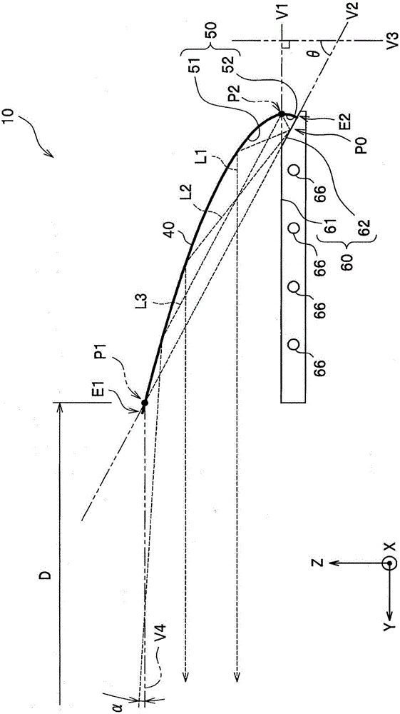
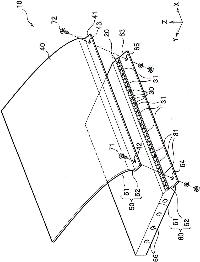
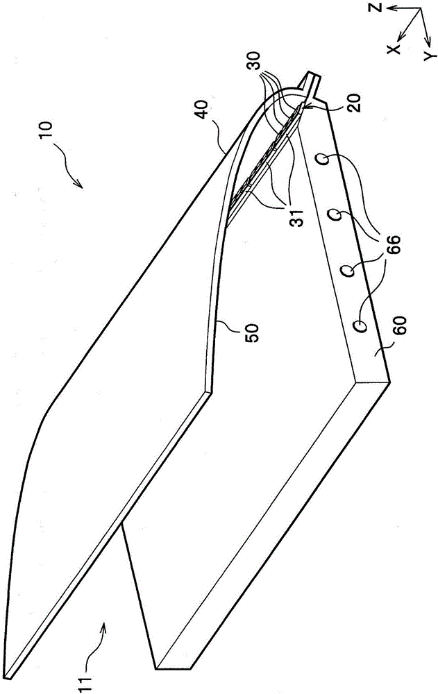
[0046] Hereinafter, an ultraviolet irradiation device for curing ink and the like will be described as an example of the light emitting device according to the first embodiment of the present invention. Such as Figure 1 to Figure 3 As shown, the light emitting device 10 of this embodiment mainly includes a light source unit 20 , a reflection unit 40 , and an installation stand 60 . Such as image 3 As shown, the light-emitting device 10 connects the reflector 40 and the installation platform 60 on the side opposite to the light irradiation direction side, and has an opening 11 formed by separating the reflection unit 40 from the installation platform 60 on the light irradiation direction side. The light emitting device 10 emits light (ultraviolet light) in the horizontal direction toward an irradiation surface that is an object separated by a predetermined distance (for example, 10 mm or more).

[0047] Hereinafter, the extending direction of the linear light source unit 20...

no. 2 approach

[0083] Figure 4 The light emitting device 10A shown with figure 2 The light emitting device 10 shown is different in that a plurality of light emitting elements 30 are arranged in two rows on the light source portion 20A. Therefore, for figure 2The same structures of the light emitting device 10 shown are denoted by the same reference numerals, and description thereof will be omitted.

[0084] The light source unit 20A includes a first light source unit 21 and a second light source unit 22 .

[0085] The first light source unit 21 is a light source unit in which a plurality of light emitting elements 30 are linearly arranged in the X direction.

[0086] The second light source unit 22 is a light source unit in which a plurality of light emitting elements 30 are linearly arranged parallel to the first light source unit 21 . The second light source unit 22 is disposed close to the first light source unit 21 .

[0087] More specifically, the first light source unit 21 and...


PUM


Abstract

The present invention provides a light emitting device which is high in peak illuminance and of which the grading performance is improved. The light emitting device includes a mount base 60, a linear light source portion 20, and a reflector 40. The mount base includes a first plane portion 61 and a second plane portion 62 that inclines with respect to the first plane portion. The light source portion is mounted on the second plane portion and includes at least one light emitting element 30. The reflector is prolonged in a prolonging direction of the linear light source portion, and includes a first reflective surface 50 and a second reflective surface 52 configured to be closer to one side of the mount base than the first reflective surface. Light emitted from the light source portion is reflected by the first reflective surface to a direction parallel with the first plane portion, namely, an irradiation direction, and the light emitted from the light source portion is reflected by the second reflective surface toward the first reflective surface.

Description

technical field [0001] The present invention relates to light emitting devices. Background technique [0002] Generally, a light emitting device using a light emitting element such as a light emitting diode (LED: Light Emitting Diode) in a light source unit has been proposed as a light source for use in various fields such as automobiles (for example, refer to Patent Documents 1 and 2). This light emitting device includes a light source unit and a reflector provided so as to focus on the light source unit, and the light source unit is detachably configured so as to be positionally adjustable with respect to the reflector (for example, refer to Patent Document 1). In addition, an ultraviolet light emitting device including a light source unit and a reflection mirror is also used in an offset printing machine that cures ink by irradiating ultraviolet rays from a light source unit. [0003] The above-mentioned conventional ultraviolet light emitting device uses a cylindrical r...

Claims


Application Information

Patent Timeline
Patent Type & Authority Applications(China)
IPC IPC(8): F21K9/20F21V7/22F21V17/10F21Y115/10
CPCF21V7/22F21V17/10F21V7/06F21V17/12F21Y2101/00F21Y2103/10F21Y2115/10F21S41/147F21S41/151F21S41/32H01L33/60F21V7/0008
Inventor 小野正人大汤孝宽
Owner NICHIA CORP
Learn More