Lamp capable of eliminating light distribution defects of multiple COB light sources and reflecting cup and method thereof

A reflective cup and defect technology, which is applied in optics, light guides, reflectors, etc., can solve the problems of large-scale lens process difficulties, high cost, and lack of light type, and achieve the goal of solving light distribution defects, prolonging service life, and low manufacturing cost Effect

Pending Publication Date: 2020-07-03
FUJIAN CAS CERAMIC OPTOELECTRONICS TECH CO LTD
View PDF8 Cites 0 Cited by
  • Summary
  • Abstract
  • Description
  • Claims
  • Application Information

AI Technical Summary

Problems solved by technology

Existing solutions: 1. Install a lens at the front end of the reflector, but due to the limitation of the size of the lens used in the reflector or the light distribution parts at the front end, there may even be cases where the lens cannot be used, and there are also cases in the manufacture of large lenses The process is difficult and the cost is high; 2. Add a light source in the middle of the circular COB luminous body, but such a light source is a special-shaped light source, and the manufacturing process of the special-shaped light source is difficult and unbalanced with the surrounding circular COB luminous body; 3. The combined The circular COB luminous body is replaced by other square and special-shaped COB luminous bodies, but the light pattern will also be missing and not full, and the manufacturing process is also difficult to achieve

Method used


Image

  • Lamp capable of eliminating light distribution defects of multiple COB light sources and reflecting cup and method thereof
  • Lamp capable of eliminating light distribution defects of multiple COB light sources and reflecting cup and method thereof
  • Lamp capable of eliminating light distribution defects of multiple COB light sources and reflecting cup and method thereof

Examples


Embodiment Construction

[0063] The embodiment of the present invention solves the technical problem in the prior art that the combination of circular COB illuminants produces light distribution defects in the reflector by providing a lamp and method for eliminating the light distribution defects of multiple COB light sources and reflector cups, and realizes It improves the technical effect of light balance.

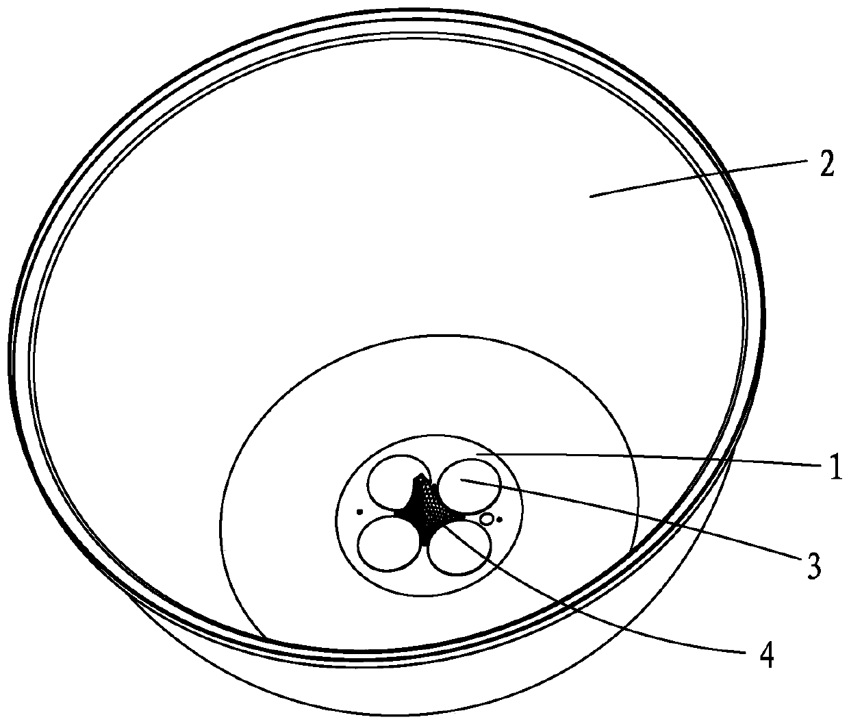
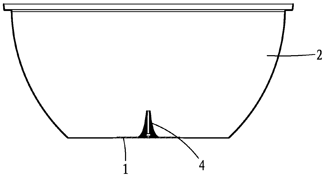
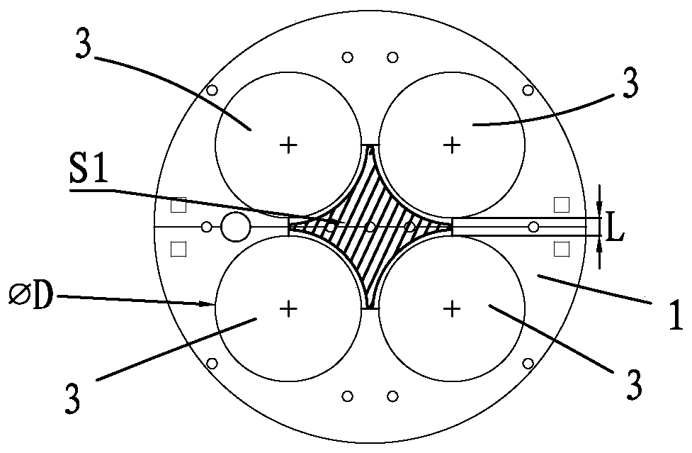
[0064] The technical solution in the embodiment of the present invention is to solve the above problems, the general idea is as follows: by adding a light guide between more than three circular COB luminous bodies, the circular COB luminous body and the light guide are both located inside the reflective cup; The bottom surface of the light guide is larger than its top surface, and there is a reflective surface between the bottom surface and the top surface, and the reflective surface corresponds to the circular COB luminous body one by one, and the sum of the areas of the reflective surfaces Gre...


PUM


Abstract

The invention provides a lamp capable of eliminating light distribution defects of multiple COB light sources and a reflecting cup and a method thereof. The lamp comprises a supporting plate fixedly arranged at the rear end of the reflecting cup, at least three circular COB luminous bodies fixedly arranged on the supporting plate, and a light guide device fixedly arranged on the supporting plate;the circular COB luminous bodies are uniformly arranged around the light guide device, and the circular COB luminous bodies and the light guide device are positioned inside the reflecting cup; and thebottom surface of the light guide device is larger than the top surface of the light guide device, reflecting surfaces are arranged between the bottom surface and the top surface, the reflecting surfaces correspond to the circular COB luminous bodies one by one, the sum of the areas of the reflecting surfaces is larger than the missing area of the bottom between the circular COB luminous bodies,and the light distribution angle of the light guide device is smaller than the light outlet angle of the reflecting cup. The lamp has the advantages that the light guide device is additionally arranged between the more than three circular COB luminous bodies, so that the problem of light distribution defects under a small luminous angle is effectively solved; and the light distribution effect is high, and the light guide device is simple in structure and low in manufacturing cost.

Description

【Technical field】 [0001] The invention relates to lighting equipment, in particular to a lamp and a method for eliminating the light distribution defects of multiple COB light sources and reflector cups. 【Background technique】 [0002] In the direction of ultra-high power, such as the kilowatt level, the development of a single circular COB luminous body is impossible to expand the luminous area infinitely due to the influence of heat or equipment. Light is weaker. Therefore, a combined light source will inevitably be used. When two or more circular COB illuminants are combined and arranged inside the reflector for light distribution, for a small luminous angle, there will be a problem of defective light patterns. Refer to Figure 8 . Existing solutions: 1. Install a lens at the front end of the reflector, but due to the limitation of the size of the lens used in the reflector or the light distribution parts at the front end, there may even be cases where the lens cannot be...

Claims


Application Information

Patent Timeline
Patent Type & Authority Applications(China)
IPC IPC(8): F21V29/71F21V5/00F21V31/00F21V7/10F21V29/51F21V13/02F21V8/00
CPCF21V29/71F21V5/00F21V31/005F21V7/10F21V29/51F21V13/02
Inventor 张修强李彦霖林晓张数江林海宝
Owner FUJIAN CAS CERAMIC OPTOELECTRONICS TECH CO LTD
Why Eureka
Try Eureka