
Design method of smart jamming noise signal based on speed dragging

A technology of interference noise and signal design, applied in radio wave measurement systems, instruments, etc., can solve the problems of poor echo sidelobe anti-jamming measures, inability to suppress interference, and radar anti-jamming cancellation, etc. To achieve the effect of enhancing deception and suppression, improving practicability, and achieving stability

Active Publication Date: 2018-04-24
HARBIN INST OF TECH
View PDF5 Cites 1 Cited by
  • Summary
  • Abstract
  • Description
  • Claims
  • Application Information

AI Technical Summary

Problems solved by technology

[0023] The purpose of the present invention is to solve the problem that when the false target track is irrelevant, it is easy to be canceled by radar anti-interference, it cannot play the role of suppressive interference, and the effect of anti-interference measures such as echo sidelobe cancellation is not good. Smart jamming noise signal design method based on velocity dragging

Method used

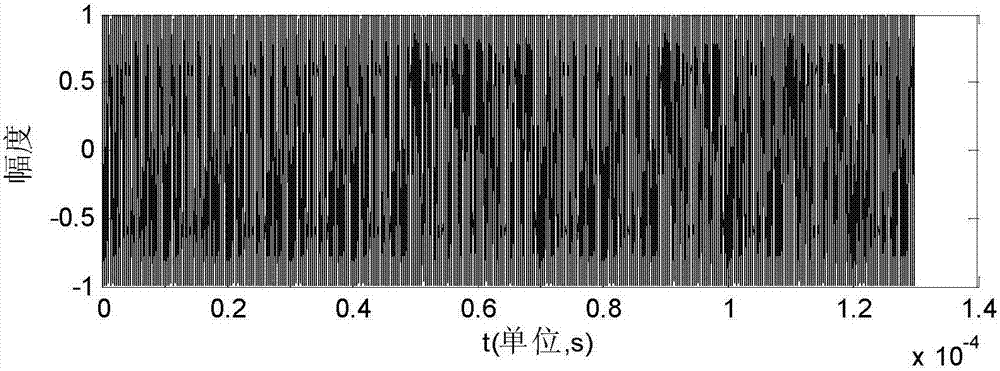
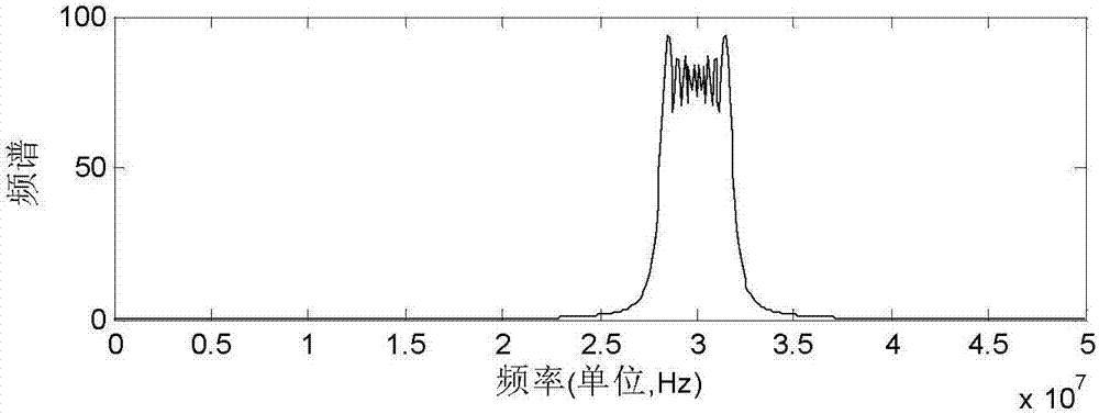
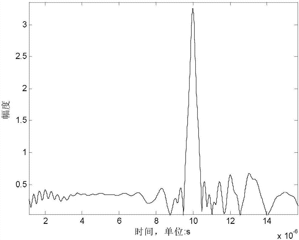

Image

  • Design method of smart jamming noise signal based on speed dragging
  • Design method of smart jamming noise signal based on speed dragging
  • Design method of smart jamming noise signal based on speed dragging

Examples


specific Embodiment approach 1

[0069] Specific embodiment one: the smart interference noise signal design method based on speed dragging in this embodiment is specifically prepared according to the following steps:

[0070] Step 1. After the interference echo simulates the electromagnetic signal emitted by the radar to irradiate the target, it returns to the radar antenna through the secondary scattering of the target; at this time, the echo signal of the target is compared with the transmitted signal of the radar. There are obvious changes in three aspects; after the electromagnetic signal emitted by the radar is irradiated to the target, the time delay τ that returns to the radar antenna after the target's secondary scattering; the size of the time delay reflects the radial distance of the target relative to the radar;

[0071] Step 2. Calculate the Doppler frequency shift f of the radar antenna after the electromagnetic signal emitted by the radar is irradiated to the target and returns to the radar anten...

specific Embodiment approach 2

[0104] Specific embodiment 2: The difference between this embodiment and specific embodiment 1 is that the time delay τ described in step 1 is specifically:

[0105] τ=2R t / c (11)

[0106] In the formula, τ is the time delay of the target echo signal relative to the transmitted signal. Other steps and parameters are the same as those in Embodiment 1.

specific Embodiment approach 3

[0107] Specific embodiment three: the difference between this embodiment and specific embodiment one or two is: the Doppler frequency shift f returned to the radar antenna through the secondary scattering of the target described in step two d Specifically:

[0108] When there is a relative radial movement between the target and the radar, the frequency of the target echo signal will change, that is, the Doppler effect occurs; due to the influence of the Doppler effect, the frequency of the target echo signal has an Doppler shift f d The expression is:

[0109]

[0110] In the formula, is the target range radar R t When is the radial velocity of the target relative to the radar. Other steps and parameters are the same as those in Embodiment 1 or Embodiment 2.


PUM


Abstract

The invention provides a smart jamming noise signal design method based on velocity pull-off and relates to the smart jamming noise signal design method. The smart jamming noise signal design method based on the velocity pull-off is put forward to solve the problem that false target track is easy to be cancelled by radar anti-interference when uncorrelated, so that the effect of suppression jamming cannot be achieved, and the effect of anti-jamming measures, such as echo sidelobe cancellation, is not good enough. The method is realized through the following steps: 1) calculating time delay tau; 2) calculating Doppler frequency shift fd obtained after an electromagnetic signal is reflected back to a radar antenna through secondary scattering of a target; 3) calculating the amplitude value At of a target echo signal at the time t after the electromagnetic signal is reflected back to the radar antenna through secondary scattering of the target; 4) calculating the target echo signal sr(t); and 5) increasing offset of the Doppler frequency shift fd. The method is applied to the smart jamming noise signal design field.

Description

technical field [0001] The invention relates to a smart interference noise signal design method, in particular to a speed drag-based smart interference noise signal design method. Background technique [0002] Assuming that the radar transmitted signal is a chirp signal s(t), its expression is: [0003] [0004] Among them, f 0 Is the carrier frequency, μ is the frequency modulation slope. Assuming that the target is a point target, the scattering cross-sectional area is σ, and the target distance is R, then the response function of the target is: [0005] h(t)=σδ(t-τ R ) (2) [0006] Among them, τ R =R / (2c), c is the speed of light, then the target echo is: [0007] [0008] Let the pulse compression factor of the signal processor be s * (-t), after matching filtering, the expression of the target echo after the pulse pressure is obtained is as follows: [0009] [0010] Let the spectrum of h(t) be H(f), and the spectrum of s(t) be S(f), then the spectrum o...

Claims


Application Information

Patent Timeline
Patent Type & Authority Patents(China)
IPC IPC(8): G01S7/38
CPCG01S7/38
Inventor 张露文白成超郭继峰
Owner HARBIN INST OF TECH
Learn More