
Display base plate and display device

A technology for display substrates and display devices, which is applied to instruments, nonlinear optics, optics, etc., can solve problems such as color mixing, and achieve the effect of avoiding color mixing problems.

Active Publication Date: 2016-09-07
BOE TECH GRP CO LTD
View PDF10 Cites 14 Cited by
  • Summary
  • Abstract
  • Description
  • Claims
  • Application Information

AI Technical Summary

Problems solved by technology

[0005] The present invention at least partially solves the problem that existing display devices using quantum dots as color filter films easily cause color mixing, and provides a display substrate and a display device that can avoid color mixing

Method used


Image

  • Display base plate and display device
  • Display base plate and display device
  • Display base plate and display device

Examples


Embodiment 1

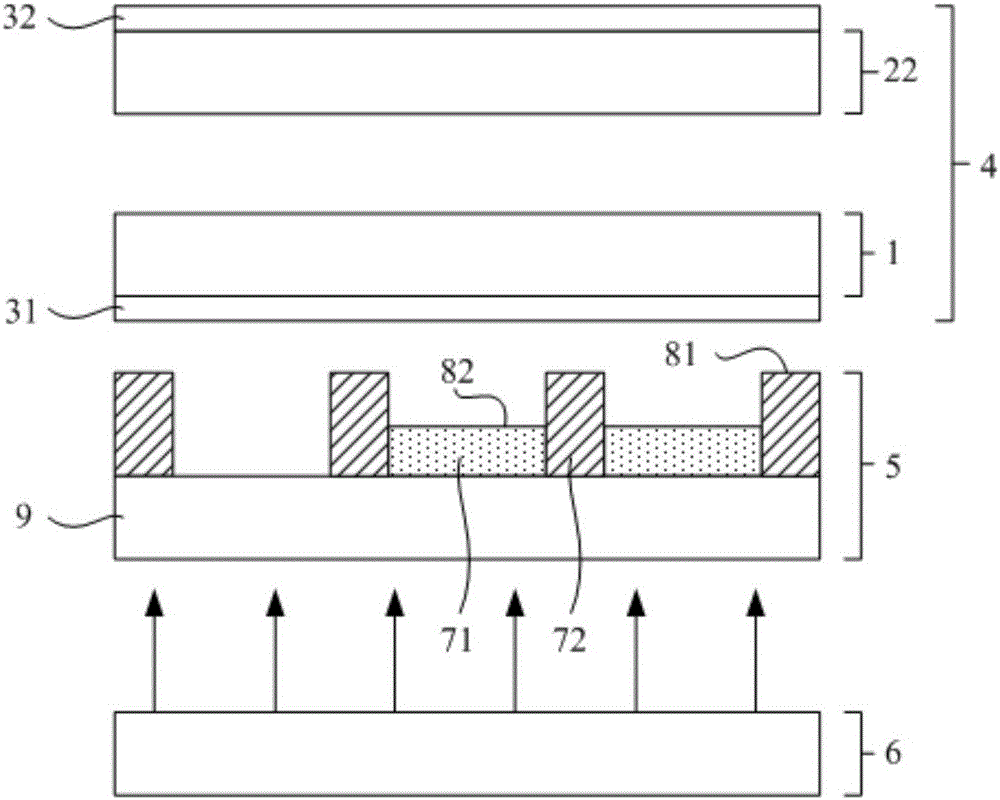
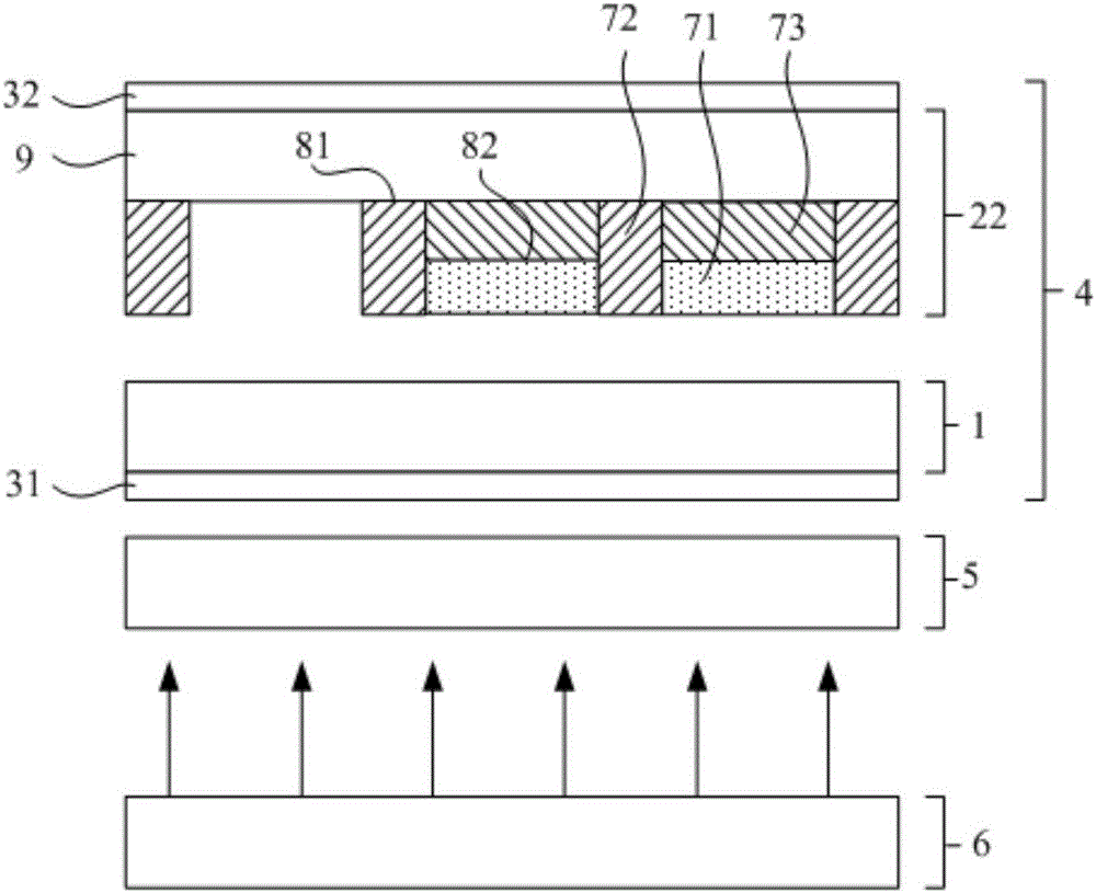
[0026] Such as figure 2 , image 3 As shown, the present embodiment provides a display substrate, which is used in a display device, and includes a base 9, one side of the base 9 is provided with a plurality of color filter films 71 of different colors, and the color filter films of each color 71 contains quantum dots that emit light of the corresponding color, and

[0027] At least part of the periphery of each color filter film 71 is provided with an opaque barrier wall 72, the barrier wall 72 has a first surface 81 facing the light-emitting surface of the display device, and the color filter film 71 has a second surface facing the light-emitting surface of the display device. Surface 82 , the first surface 81 is closer to the light-emitting surface of the display device than the second surface 82 .

[0028] The display substrate of this embodiment is used in a display device, which includes a color filter film 71 containing quantum dots, and an opaque barrier wall 72 is ...

Embodiment 2

[0050] Such as figure 2 , image 3 As shown, this embodiment provides a display device, which includes:

[0051] The above-mentioned display substrate;

[0052] A backlight 6 (preferably a blue-emitting backlight 6).

[0053] The above display substrate can be used in a display device, so as to prevent color mixing. Specifically, the display substrate can be used as the array substrate 1 in the liquid crystal display panel 4 or the box-to-box substrate 22 (possibly a color filter substrate) that is boxed with the array substrate 1, and can also be used as the The short waves in between pass through the reflective substrate 5 and so on.

[0054] Of course, the display device may also include other structures such as the upper polarizer 32 , a power supply, a driving chip, a frame, etc., which will not be described in detail here.

[0055] Specifically, the display device can be any product or component with a display function, such as electronic paper, mobile phone, table...


PUM


Abstract

The invention provides a display base plate and a display device, and belongs to the technical field of quantum dot display, which aims at partially solving the technical problem of easiness in color mixing in the existing display device by using the quantum dot as a color filter film. The display base plate is arranged in the display device, and comprises a substrate, wherein a plurality of color filter films with different colors are arranged at one side of the substrate; the color filter films with different colors are used for emitting quantum dots of light with applicable color; an opaque retaining wall is arranged on part of periphery of each color filter film, and is provided with a first surface facing the light emitting surface of the display device; each color filter film is provided with a second surface facing the light emitting surface of the display device; compared with the second surface, each first surface is closer to the light emitting surface of the display device.

Description

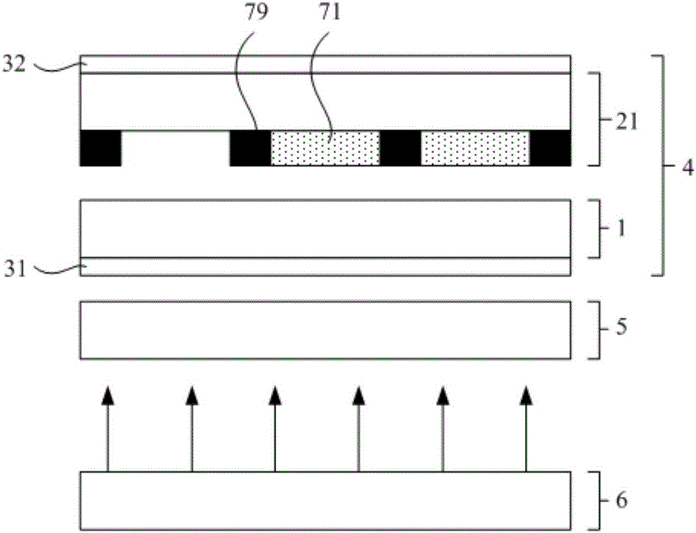
technical field [0001] The invention belongs to the technical field of quantum dot display, and in particular relates to a display substrate and a display device. Background technique [0002] Quantum dots (QD, Quantum Dot) refer to granular materials with three-dimensional dimensions on the order of nanometers. Due to their special size, quantum dots have many special properties. For example, quantum dots can enter an excited state when illuminated, and emit light of a specific wavelength (that is, a specific color) when the excited state falls back to the ground state. [0003] Due to the above properties of quantum dots, they have been widely used in display devices. For example, if figure 1 The shown display device includes a backlight source 6 and a liquid crystal display panel 4, the liquid crystal display panel 4 includes an array substrate 1 and a color filter substrate 21 in a box, a liquid crystal layer is arranged between the two substrates, and a wire grid type...

Claims


Application Information

Patent Timeline
IPC IPC(8): G02F1/1335G02F1/13357
CPCG02F1/133514G02F1/1336G02F1/133614
Inventor 石戈田允允崔贤植林允植方正祝明
Owner BOE TECH GRP CO LTD
Learn More