A Method for Obtaining the Temperature of the First and Second Deformation Zones in High Speed ​​Cutting

A technology for high-speed cutting and acquisition methods, which is applied in the directions of instruments, calculations, and electrical digital data processing, etc. It can solve the problems of inability to obtain the temperature of the first and second deformation zones, the inability to finely distinguish the high-gradient temperature field in the micro-zone, and the small area of ​​the cutting zone. and other issues, to achieve the effect of low cost, good applicability, low cost and fast

Active Publication Date: 2019-01-04
BEIJING FORESTRY UNIVERSITY
View PDF3 Cites 0 Cited by
  • Summary
  • Abstract
  • Description
  • Claims
  • Application Information

AI Technical Summary

Problems solved by technology
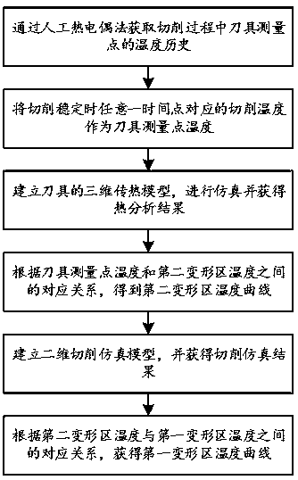
[0005] For the acquisition of cutting temperature, common methods include natural thermocouple method, artificial thermocouple method, and thermal radiation method. Subdivision; the artificial thermocouple method can only obtain the temperature of the workpiece or tool measurement point, but cannot obtain the temperature of the first and second deformation zones; the thermal radiation method can obtain the temperature field, but because the cutting area is small, it cannot finely distinguish the high gradient of the micro-area Temperature Field

Method used


Image

  • A Method for Obtaining the Temperature of the First and Second Deformation Zones in High Speed ​​Cutting
  • A Method for Obtaining the Temperature of the First and Second Deformation Zones in High Speed ​​Cutting
  • A Method for Obtaining the Temperature of the First and Second Deformation Zones in High Speed ​​Cutting

Examples


Embodiment Construction

[0037] In order to facilitate the understanding of the present invention, the present invention will be described more fully below with reference to the relevant drawings. The preferred embodiments of the invention are shown in the drawings. However, the present invention can be implemented in many different forms and is not limited to the embodiments described herein. On the contrary, the purpose of providing these embodiments is to make the understanding of the disclosure of the present invention more thorough and comprehensive.

[0038] Unless otherwise defined, all technical and scientific terms used herein have the same meaning as commonly understood by those skilled in the technical field of the present invention. The terms used in the specification of the present invention herein are only for the purpose of describing specific embodiments, and are not intended to limit the present invention.

[0039] In this embodiment, high-speed right-angle cutting of Ti-6Al-4V titanium ...


PUM


Abstract

The invention relates to the technical field of high-speed cutting, and discloses a method for acquiring the temperature of a first deformation area and a second deformation area in high-speed cutting. The method includes: firstly, acquiring a temperature history of a tool measurement point during cutting through a manual thermocouple method; using the cutting temperature corresponding to any time point as the temperature of the tool measurement point and obtaining a temperature curve of the measurement point in a corresponding time duration in the condition of a stable cutting temperature according the temperature history; establishing a three-dimensional heat transfer model of a tool, and performing simulation and obtaining a heat analysis result; obtaining the temperature of the tool measurement point and the temperature of the second deformation area through analysis, acquiring a corresponding relationship between the temperature of the tool measurement point and the temperature of the second deformation area, and acquiring a temperature curve of the second deformation area according to the temperature curve of the measurement point; establishing a two-dimensional cutting simulation model, and acquiring a cutting simulation result; and acquiring a corresponding relationship between the temperature of the first deformation area and the temperature of the second deformation area in the condition of the stable cutting temperature through analysis, and then acquiring a temperature curve of the first deformation area. The method is simple, reliable, and is wide in application.

Description

Technical field [0001] The invention relates to the technical field of high-speed cutting, and more specifically, to a method for obtaining the temperature of the first and second deformation zones of high-speed cutting. Background technique [0002] High-speed cutting uses high-strength tools to improve the material removal rate, machining accuracy and quality of the machined surface by increasing the cutting speed and feed rate. It is an advanced manufacturing technology with high efficiency, high quality and low cost. [0003] In view of the advantages of high-speed cutting, it is of great significance to study the high-speed cutting mechanism in depth, and the cutting temperature is an important part of the high-speed cutting mechanism. For a long time, the cutting temperature is a fuzzy concept: the cutting heat is distributed on the workpiece, the tool, the chip and the cutting zone in the form of a field, but each temperature is collectively called the cutting temperature. ...

Claims


Application Information

Patent Timeline
Patent Type & Authority Patents(China)
IPC IPC(8): G06F17/50
CPCG06F30/367G06F2119/08
Inventor 徐道春熊丹萍杨文远李文熙
Owner BEIJING FORESTRY UNIVERSITY
Why Eureka
Try Eureka