Cutting force modeling method suitable for high-speed turning process of difficult machining material

A modeling method and cutting force technology, applied in the field of metal cutting, can solve the problems of different deformation thickness and small cutting parameters in the cutting area.

Inactive Publication Date: 2016-09-07
HUAZHONG UNIV OF SCI & TECH
View PDF2 Cites 4 Cited by
  • Summary
  • Abstract
  • Description
  • Claims
  • Application Information

AI Technical Summary

Problems solved by technology

However, considering that the cutting parameters are usually relatively small in the high-speed cutting process, especially for difficult-to-machine materials, the CBN tool mainly participates in the cutting with the arc edge during the whole cutting process, which leads to different deform

Method used


Image

  • Cutting force modeling method suitable for high-speed turning process of difficult machining material
  • Cutting force modeling method suitable for high-speed turning process of difficult machining material
  • Cutting force modeling method suitable for high-speed turning process of difficult machining material

Examples


Embodiment Construction

[0036] In order to make the object, technical solution and advantages of the present invention clearer, the present invention will be further described in detail below in conjunction with the accompanying drawings and embodiments. It should be understood that the specific embodiments described here are only used to explain the present invention, not to limit the present invention. In addition, the technical features involved in the various embodiments of the present invention described below can be combined with each other as long as they do not constitute a conflict with each other.

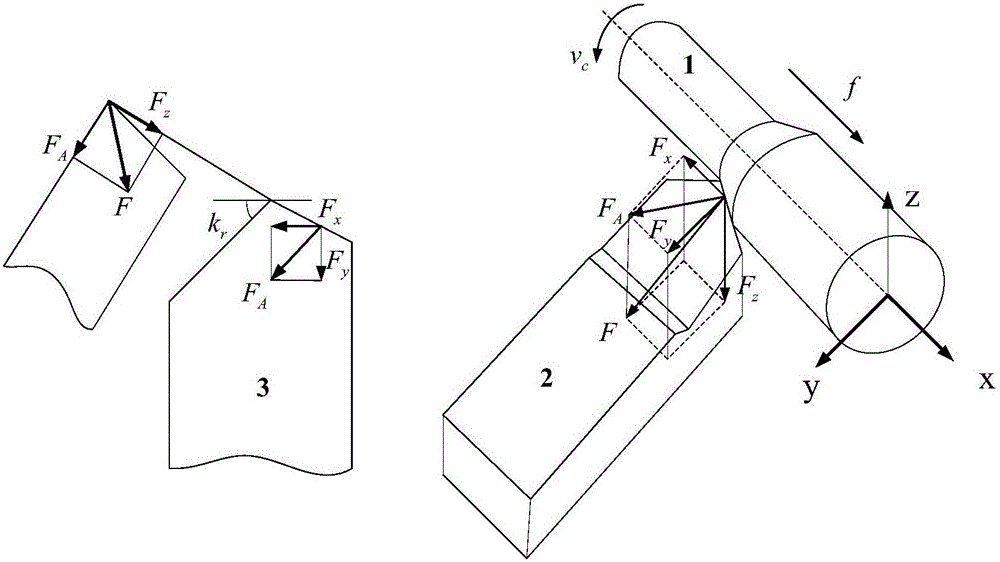
[0037] figure 2 It is a schematic diagram used to show the cutting force and component force in the turning process. Such as figure 2 shown in , where F x , F y , F z are the component forces of the cutting force in the direction of feed speed, cutting thickness direction and cutting speed direction, respectively. However, since the cutting tool has a nose radius, when the cutting tool i...


PUM


Abstract

The invention belongs to the technical field associated with metal turning machining, and discloses a cutting force modeling method suitable for a high-speed turning process of a difficult machining material. The cutting force modeling method comprises the following steps: (i) constructing an expression to reflect a cutting thickness change situation in a whole turning process; (ii) aiming at the cutting force, independently representing and calculating a corresponding dynamic cutting force coefficient along cutting, radial and axial directions; and (iii) combining with the obtained dynamic cutting thickness and the obtained dynamic cutting force coefficient, establishing a cutting force model which can truly reflect the high-speed turning process of the difficult machining material. Through the cutting force modeling method, the cutting force in the integral high-speed turning process can be more comprehensively and accurately predicted, the cutting process is efficiently controlled at a high quality, and targeted technical guidance is provided.

Description

technical field [0001] The invention belongs to the technical field related to metal cutting, and more specifically relates to a cutting force modeling method suitable for high-speed turning of difficult-to-machine materials. Background technique [0002] With the continuous advancement of science and technology and the continuous development of human society, the high-quality requirements of parts make the manufacturing industry pay more and more attention to the efficient processing of materials, and more and more difficult-to-process materials appear, especially in aerospace, nuclear Industry, military industry and other fields. Difficult-to-machine materials have excellent characteristics, but they also bring difficulties to turning. The microstructure contains carbide hard spots, low thermal conductivity, small specific heat capacity, high temperature strength, high shear stress, and high viscosity, resulting in large cutting forces. , The cutting temperature is high, ...

Claims


Application Information

Patent Timeline
IPC IPC(8): G06F19/00
CPCG16Z99/00
Inventor 张小明黄志阳丁汉庄可佳陈丁曹畅何少杰刘凤竹
Owner HUAZHONG UNIV OF SCI & TECH
Why Eureka
Try Eureka