
motor control unit

A technology of a control device and a motor, which is applied in the direction of motor generator control, electronic commutation motor control, control of electromechanical transmission devices, etc., and can solve the problems of increased interference torque and noise.

Inactive Publication Date: 2020-05-08
SANYO DENKI CO LTD +1
View PDF1 Cites 0 Cited by
  • Summary
  • Abstract
  • Description
  • Claims
  • Application Information

AI Technical Summary

Problems solved by technology

Especially when the resolution of the encoder is low, the noise of estimating the disturbance torque becomes large

Method used


Image

  • motor control unit
  • motor control unit
  • motor control unit

Examples


Embodiment Construction

[0033] In the following detailed description, for purposes of explanation, numerous specific details are set forth in order to provide a thorough understanding of the disclosed embodiments. It may be evident, however, that one or more embodiments may be practiced without these specific details. In other instances, well-known structures and devices are shown schematically in order to simplify the drawings.

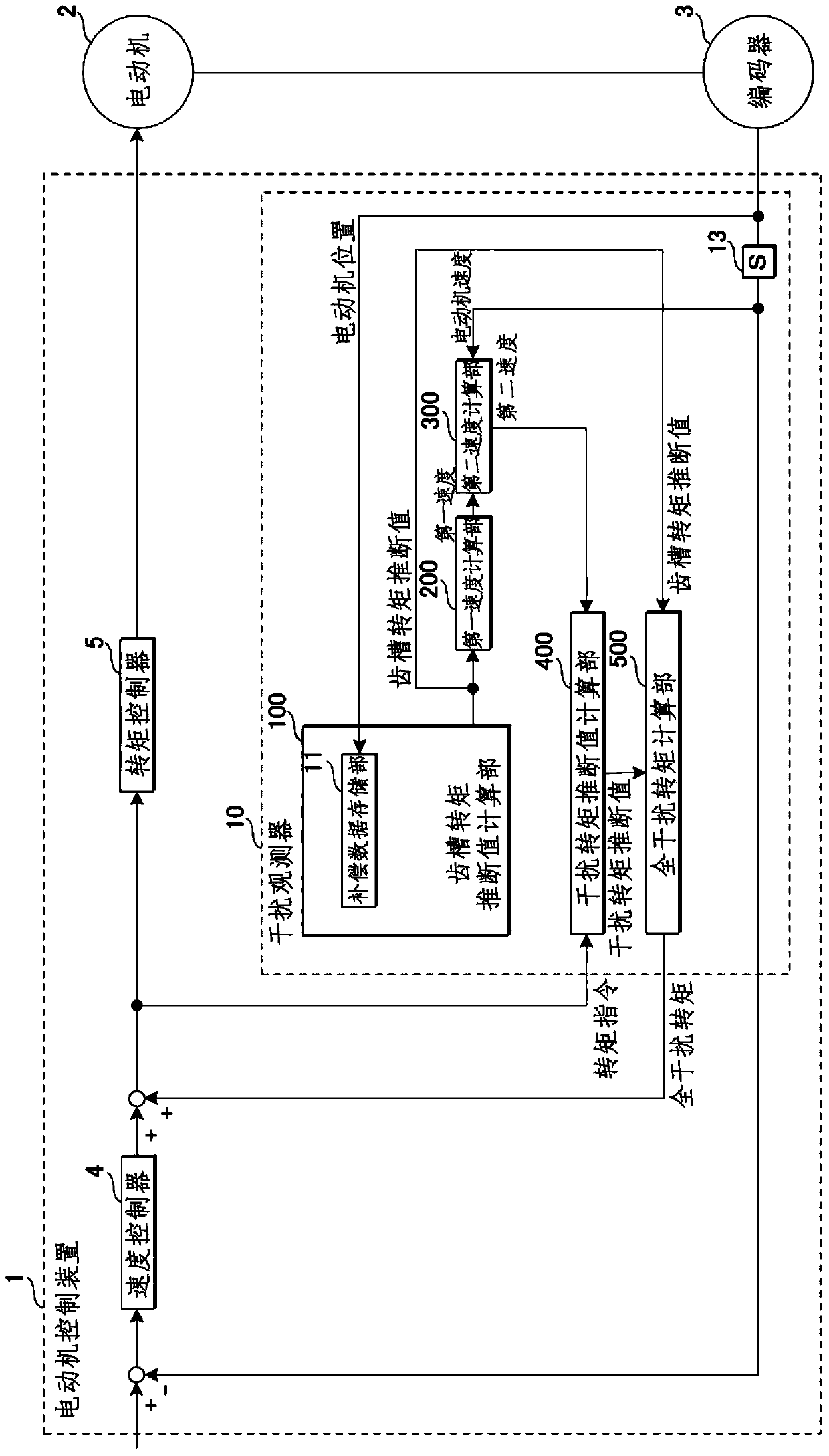
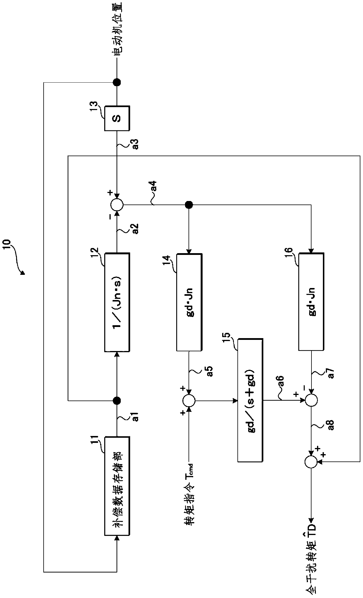
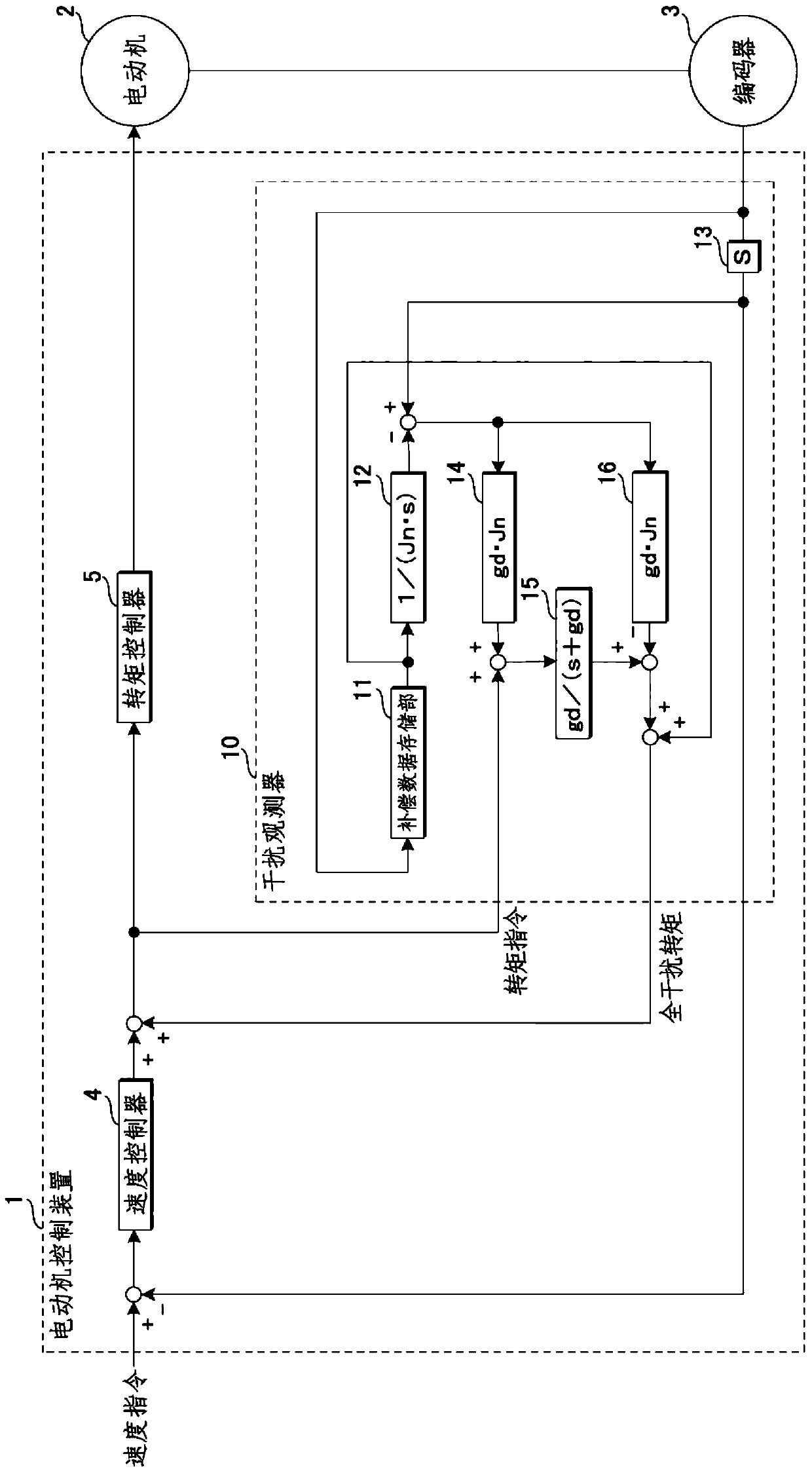
[0034] Such as figure 1 As shown, the motor control device 1 of the present embodiment includes a compensation data storage unit 11 and a disturbance observer 10 . The compensation data storage unit 11 stores cogging torque data (cogging torque data) corresponding to the position of the motor 2 as data for suppressing torque fluctuation of the motor 2 due to the cogging torque.

[0035] The disturbance observer 10 acquires the position of the motor 2 . The disturbance observer 10 calculates an estimated cogging torque value from the acquired motor position based on the ...


PUM


Abstract

A motor control device includes: a compensation data storage unit in which data corresponding to changes in torque of a motor due to cogging torque is stored; and a disturbance observer configured to calculate a cogging torque estimated value in accordance with the position of the motor to make disturbance suppression compensation on the basis of the calculated cogging torque estimated value. This can prevent the influence of friction and the like and reduce speed ripple and torque ripple of the motor.

Description

technical field [0001] The present invention relates to a motor control device for estimating and suppressing motor disturbance. Background technique [0002] Due to the requirements of fine processing, etc., the machine tool needs to maintain a high processing quality. Therefore, high precision is required for motor driving. In addition, in order to shorten the cycle time, the positioning time needs to be shortened. [0003] On the other hand, motors also need to be miniaturized. When reducing the size of the motor, the cogging torque may increase due to the constraints of the motor structure. Torque fluctuations caused by such cogging torque become disturbances during machining. Torque ripple caused by cogging torque will reduce the surface accuracy of the workpiece, or become a disturbance during positioning, resulting in a change in positional deviation. The cycle time of the machine is extended because the variation of the positional deviation delays the positionin...

Claims


Application Information

Patent Timeline
Patent Type & Authority Patents(China)
IPC IPC(8): H02P21/05H02P21/18H02P21/20H02P21/13G05B13/02
CPCG05B13/02H02P21/05H02P21/13
Inventor 大石洁横仓勇希关喜亮井出勇治仓石大悟高桥昭彦平出敏雄
Owner SANYO DENKI CO LTD
Learn More