
Self-lubricating bevel gear provided with oil storage cavity

A technology of bevel gears and oil storage chambers, applied to components with teeth, belts/chains/gears, gear lubrication/cooling, etc., can solve the problem of reducing the strength of bevel gears, and the teeth cannot be lubricated and oiled out The small hole is easy to be blocked and other problems

Pending Publication Date: 2016-09-14
TAIZHOU JINXIN MACHINERY
View PDF8 Cites 1 Cited by
  • Summary
  • Abstract
  • Description
  • Claims
  • Application Information

AI Technical Summary

Problems solved by technology

Chinese utility model patent CN201520117750.7 discloses a bevel gear shaft for vehicles, which has a self-lubricating structure and can continuously provide lubricating oil for the bevel gear, but it needs to open holes on the bevel gear, which will cause Local stress concentration occurs, thereby reducing the strength of the bevel gear, and the oil outlet hole is easily blocked, resulting in the teeth around it not being well lubricated

Method used


Image

  • Self-lubricating bevel gear provided with oil storage cavity
  • Self-lubricating bevel gear provided with oil storage cavity
  • Self-lubricating bevel gear provided with oil storage cavity

Examples


Embodiment 1

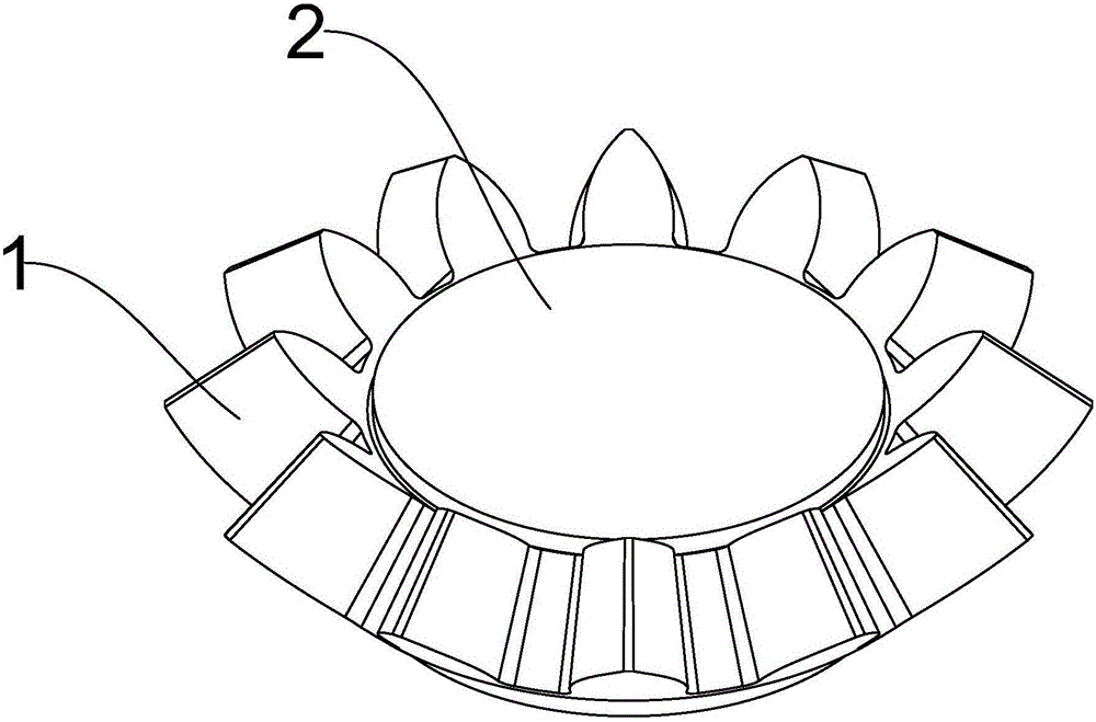
[0020] Such as figure 1 As shown, a self-lubricating bevel gear with an oil storage chamber includes a bevel gear body 1 and an oil distribution cover 2,

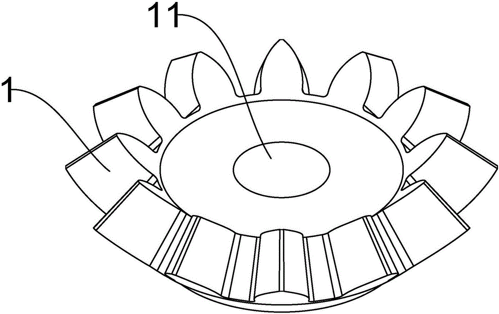
[0021] Such as figure 2 As shown, the center of the top of the bevel gear body 1 is provided with an oil storage chamber 11, the oil storage chamber 11 is cylindrical, and the end is provided with internal threads; the oil storage chamber 11 is filled with lubricating oil;

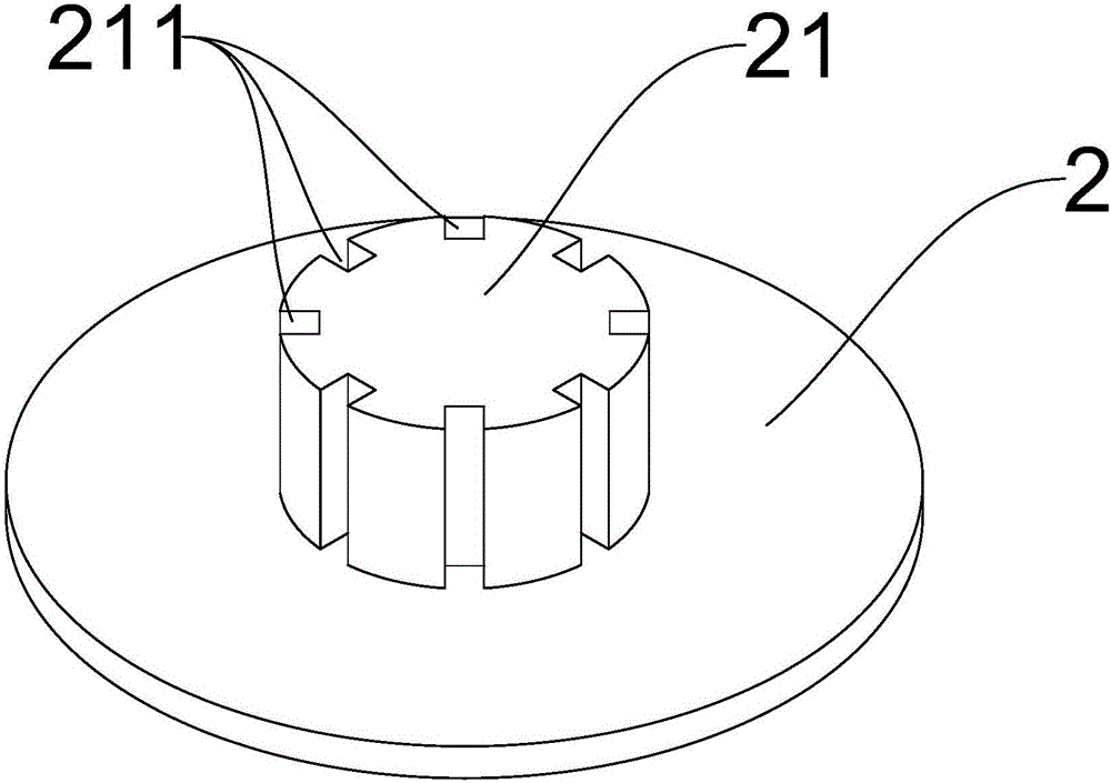
[0022] Such as image 3 As shown, the oil distribution cover 2 has a circular structure; the bottom of the oil distribution cover 2 is provided with a plunger 21, and the surface of the plunger 21 is uniformly provided with a plurality of oil outlet grooves 211, and the oil outlet grooves 211 are arranged along the column. The central axis of the plug 21 is evenly distributed and the central axis of the oil outlet groove 211 and the plunger 21 are parallel to each other, and the oil outlet groove 211 runs through both ends of the plunger 21;

[0023...

Embodiment 2

[0027] On the basis of the first embodiment, the edge of the oil separator plate 2 is pressed against the tooth root of the bevel gear body 1 . By designing the diameter of the oil-separating cover plate 2, its edge can be pressed on the tooth root, so that its edge can be lifted slightly, so that the gap between the position closer to the edge on the oil-separating cover plate 2 and the end surface of the bevel gear body 1 The larger the , the resistance to the flow of lubricating oil can be reduced to a certain extent, so that this self-lubricating bevel gear with an oil storage chamber can be applied to occasions with slower speeds; in the first embodiment, under the action of vibration , the plunger 21 is easy to fall off from the oil storage chamber 11, and the structure disclosed in the second embodiment can play a role similar to a gasket, which can greatly reduce the plunger 21 from the oil storage chamber 11. probability of falling out.


PUM


Abstract

The invention discloses a self-lubricating bevel gear provided with an oil storage cavity. The self-lubricating bevel gear provided with the oil storage cavity comprises a bevel gear body. The oil storage cavity is formed in the center of the top of the bevel gear body and is cylindrical. An inner thread is arranged at the end of the oil storage cavity. Lubricating oil is contained in the oil storage cavity. The self-lubricating bevel gear provided with the oil storage cavity further comprises an oil distribution cover plate which is of a round structure. A plunger is arranged at the bottom of the oil distribution cover plate, and a plurality of oil outlet grooves are evenly formed in the surface of the plunger. The self-lubricating bevel gear provided with the oil storage cavity has the advantages that the self-lubricating bevel gear provided with the oil storage cavity is provided with the plunger provided with the oil outlet groove structures, and the oil distribution cover plate; and when the bevel gear rotates, the lubricating oil flows out along the oil outlet grooves under the action of centrifugal force and then slowly and evenly flows out of clearances between the oil distribution cover plate and the end face of the bevel gear, afterwards, the lubricating oil is cast to the bevel gear, and therefore the self-lubricating function is achieved.

Description

technical field [0001] The invention relates to a self-lubricating bevel gear, more precisely a self-lubricating bevel gear with an oil storage cavity. Background technique [0002] In order to prevent the gears from wearing out rapidly during operation, it is necessary to add lubricating oil to the gears regularly. Chinese utility model patent CN201520117750.7 discloses a bevel gear shaft for vehicles, which has a self-lubricating structure and can continuously provide lubricating oil for the bevel gear, but it needs to open holes on the bevel gear, which will cause Local stress concentration is generated, thereby reducing the strength of the bevel gear, and the small hole for oil outlet is easily blocked, so that the nearby gear teeth cannot be lubricated well. Contents of the invention [0003] The present invention mainly solves the technical problems existing in the prior art, thereby providing a plunger with an oil outlet groove structure and an oil separation seal ...

Claims


Application Information

Patent Timeline
Patent Type & Authority Applications(China)
IPC IPC(8): F16H55/17F16H57/04
CPCF16H55/17F16H57/0427
Inventor 陈茂进陈国华
Owner TAIZHOU JINXIN MACHINERY
Learn More