Electron multiplier body, photomultiplier tube, and photomultiplier

A technology of electron multiplication and electrons, which is applied in the direction of electron multiplier tubes, electron multiplier details, dynodes, etc., can solve problems such as shapes without any consideration, and achieve the effect of improving the efficiency of multiplication

Active Publication Date: 2016-09-14
HAMAMATSU PHOTONICS KK
View PDF5 Cites 2 Cited by
  • Summary
  • Abstract
  • Description
  • Claims
  • Application Information

AI Technical Summary

Problems solved by technology

However, in the electron multiplier described in Patent Document 1, no consideration is given to the shape of the path for improving the electron multiplication efficiency.

Method used


Image

  • Electron multiplier body, photomultiplier tube, and photomultiplier
  • Electron multiplier body, photomultiplier tube, and photomultiplier
  • Electron multiplier body, photomultiplier tube, and photomultiplier

Examples


Embodiment Construction

[0047] Hereinafter, an embodiment of the present invention will be described in detail with reference to the accompanying drawings. In addition, in each figure, the same code|symbol is attached|subjected to the same or corresponding part, and the overlapping description is abbreviate|omitted.

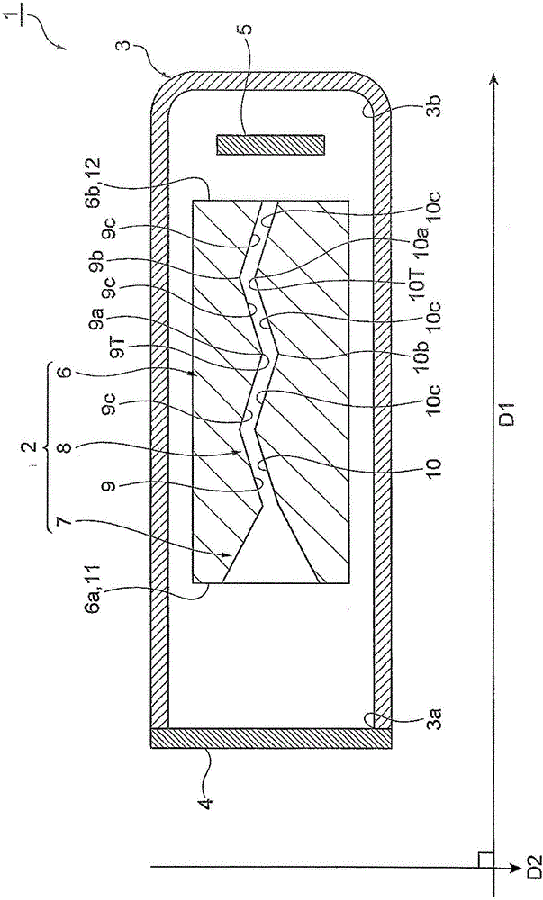
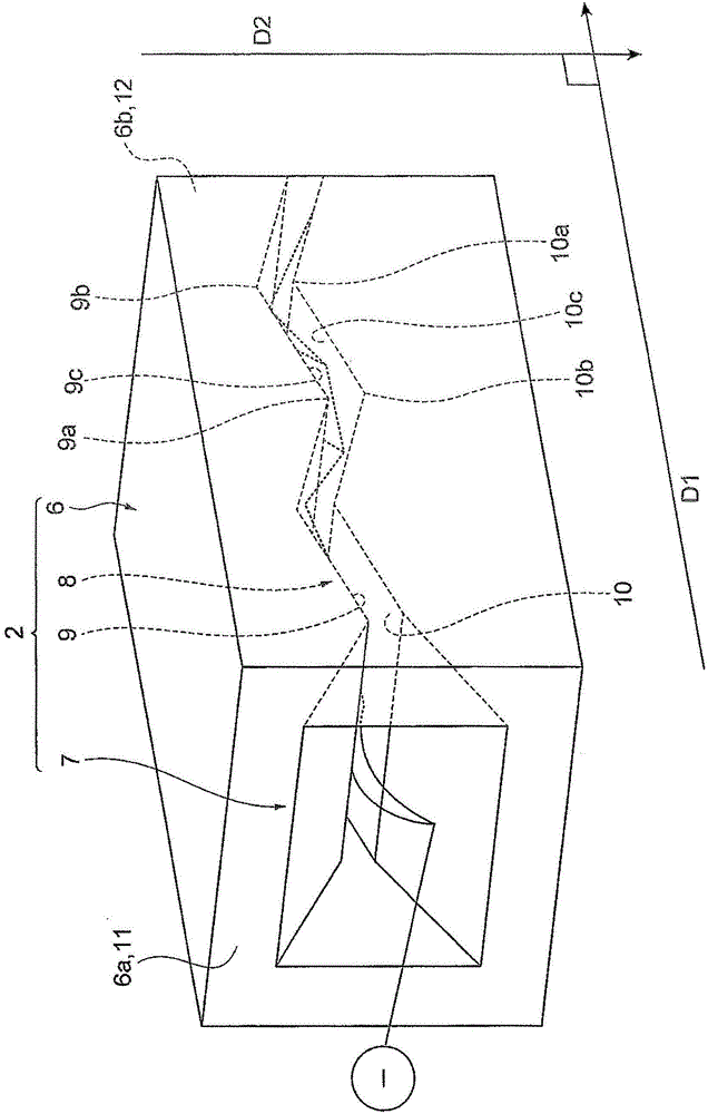
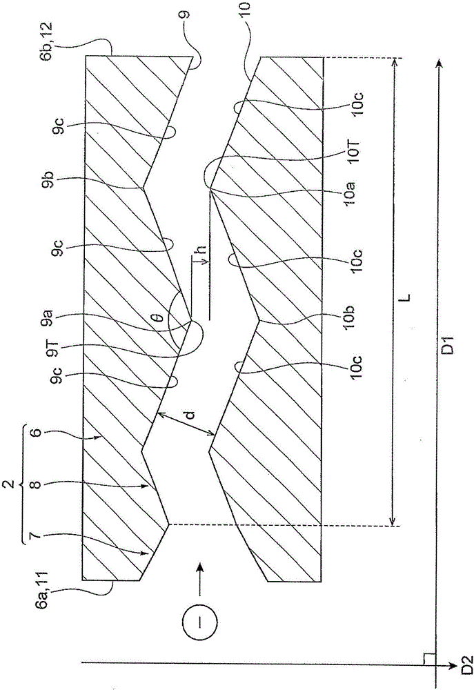
[0048] figure 1 is a cross-sectional view of the photomultiplier tube of this embodiment, figure 2 Yes figure 1 Stereoscopic view of the electron multiplier in , image 3 is a schematic representation figure 2 Cross-sectional view of the electron multiplier shown. like Figure 1 to Figure 3 As shown, the photomultiplier tube 1 includes an electron multiplier 2 , a tube body 3 , a photoelectric surface 4 , and an anode 5 .

[0049]The electron multiplier 2 emits secondary electrons in response to the incidence of electrons, thereby multiplying the electrons. The electron multiplier 2 has a main body portion 6 , an electron incident portion 7 , and a channel 8 .

[0050] The mai...


PUM


Abstract

An electron multiplier body, a photomultiplier tube, and a photomultiplier are disclosed. The invention provides the electron multiplier body including a main body portion, an electron incidence portion provided in the main body portion to be opened at one end surface of the main body portion in the first direction, and a channel provided in the main body portion to be opened at the other end surface of the main body portion in the first direction and reach the electron incidence portion and configured to emit secondary electrons, in which the channel includes a first inner surface and a second inner surface facing each other, the first inner surface includes a convex first bent portion and a concave second bent portion, and a plurality of first inclined surfaces, the second inner surface includes a convex third bent portion and a concave fourth bent portion, and a plurality of second inclined surfaces, and an interval between a tip of the first bent portion and a tip of the third bent portion, a distance between the first inclined surface and the second inclined surfaces facing each other, an angle between a pair of first inclined surfaces defining the first bent portion, and a length of the channel satisfy predetermined expressions.

Description

technical field [0001] The present invention relates to an electron multiplier, a photomultiplier tube, and a photomultiplier. Background technique [0002] Electron multipliers are described in Patent Document 1 (US Pat. No. 3,244,922). The electron multiplier includes a wavy channel extending along the longitudinal direction of the rectangular parallelepiped block. A secondary electron emission layer made of a semiconductor is provided on the inner surface of the via. [0003] However, in the above-described electron multiplier, the electrons accelerated by the potential difference collide with the inner surface of the passage, thereby releasing secondary electrons. Here, the multiplying efficiency of electron hopefuls in the electron multiplier increases. However, the electron multiplier described in Patent Document 1 does not give any consideration to the shape of the path for improving the electron multiplying efficiency. SUMMARY OF THE INVENTION [0004] The pres...

Claims


Application Information

Patent Timeline
Patent Type & Authority Applications(China)
IPC IPC(8): H01J43/04H01J43/28
CPCH01J43/04H01J43/28H01J43/24H01J43/16
Inventor 服部真也须山本比吕小林浩之
Owner HAMAMATSU PHOTONICS KK
Why Eureka
Try Eureka