An automatic umbrella

An automatic and umbrella technology, applied in umbrellas, travel products, clothing, etc., can solve problems such as inconvenience, safety accidents, and battery consumption, and achieve the effects of reducing costs, avoiding safety accidents, and improving reliability.

Inactive Publication Date: 2016-09-21
陈传扬
View PDF9 Cites 3 Cited by
  • Summary
  • Abstract
  • Description
  • Claims
  • Application Information

AI Technical Summary

Problems solved by technology

Therefore, the structure of this umbrella must use a drive motor with a large torque, which will cause the problem of increased cost, and because the larger the torque, the more the battery will be consumed, and the user needs to frequently replace the battery or charge the battery. very inconvenient
In addition, when opening or retracting the umbrella, due to the restoring force of the umbrella opening spring or the umbrella retracting spring, there may be accidental operation sometimes, which may easily lead to safety accidents

Method used


Image

  • An automatic umbrella
  • An automatic umbrella
  • An automatic umbrella

Examples


Embodiment 1

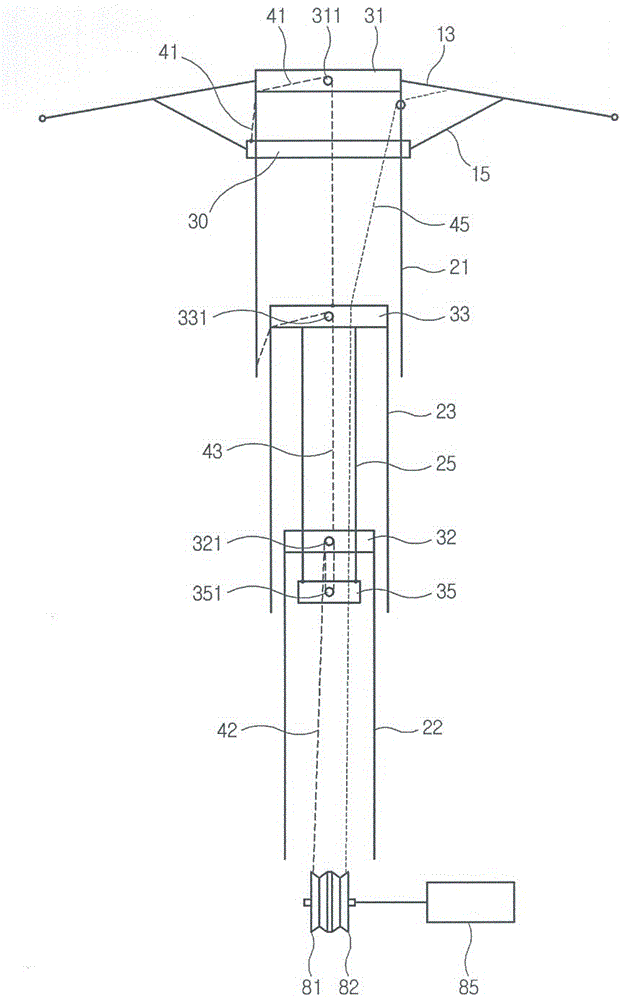
[0033] Example 1 : Three-fold umbrella

[0034] Such as Figure 1 to Figure 4 As shown, the automatic umbrella of the present invention includes: a middle rod, an umbrella handle (not shown in the figure) fixed on the bottom of the middle rod, an upper nest 31 fixed on the top of the middle rod, slidingly sleeved in the middle The lower nest 30, the first umbrella rib 13, the second umbrella rib 15, and the automatic opening and closing umbrella device outside the stick.

[0035] In the three-fold umbrella, the middle rod is made of three pipe fittings, one section of upper tube 21, one section of middle tube 23 and one section of lower tube 22. According to the size of the pipe diameter, it is socketed from outside to inside in turn, and the adjacent pipes that are socketed can slide up and down relative to each other so as to realize the extension and folding of the middle rod (the same below).

[0036] In Embodiment 1, when the middle rod is extended, the upper tube ...

Embodiment 2

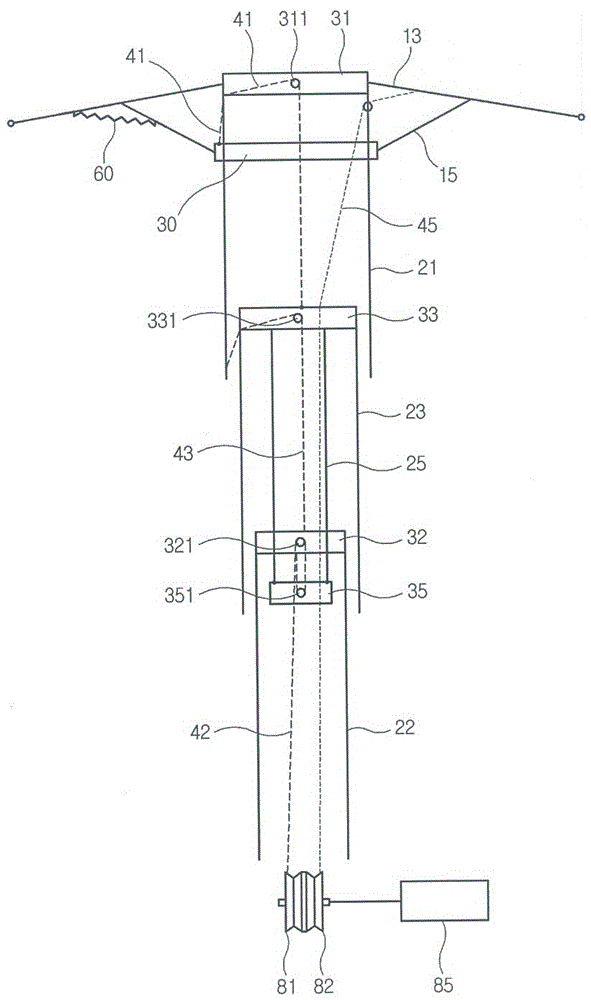
[0063] Example 2 : two-fold umbrella

[0064] Emphatically illustrate the place that the embodiment of this two-fold umbrella is different from embodiment 1 below.

[0065] Such as Figure 5 and Figure 6 As shown, in the second embodiment, the middle rod is formed by two pipe fittings, one section of upper tube 121 and one section of lower tube 122 , which are slidably socketed inside and outside according to the diameter of the pipe. The parachute opening cords include two cords, a first parachute opening cord 141 and a second parachute opening cord 142 . Similarly, a movable part 135 is provided in the cavity of the lower tube 122 , and a push rod 125 is provided between the movable part 135 and the upper tube 121 .

[0066] One end of the first parachute opening pull cord 141 is connected to the lower nest 130, and the other end goes around the upper nest pulley 1311 fixed at the upper nest 131 on the top of the upper tube 121 and then enters the inner cavity of th...

Embodiment 3

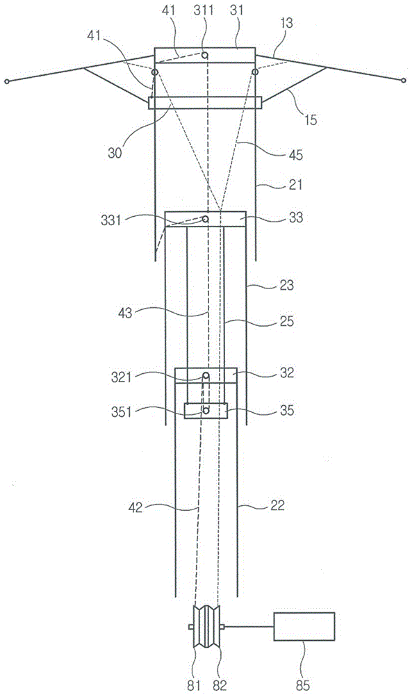
[0071] Example 3 : Straight bone umbrella

[0072] Such as Figure 7 and Figure 8 As shown, in this embodiment, the middle rod is a single pipe 221, and the parachute-opening pull cord is a single pull cord 24, and there is no need to arrange movable parts and push rods in the middle rod.

[0073] One end of the pull cord 24 for opening the umbrella is connected to the lower nest 230, and the other end goes around the upper nest pulley 2311 fixed at the upper nest 231 on the top of the middle rod 221, enters the inner cavity of the middle rod 221 and connects to the first reel 81. One end of the umbrella retracting pull cord 245 is connected to the second reel 82, and the other end is wound upward along the inner cavity of the middle rod 221, passes through the middle rod pulley 2312 provided on the upper side wall of the middle rod 221, and then is drawn out to connect to the first umbrella. bone13.

[0074]When retracting the umbrella, the driver 85 starts to rotate...


PUM


Abstract

The invention relates to an automatic umbrella comprising a middle rod, an umbrella handle, an upper nest, a lower nest, first umbrella ribs with the inner ends connected with the upper nest, second umbrella ribs with the two ends connected with the lower nest and the first umbrella ribs, and an automatic umbrella opening and closing device. The automatic umbrella opening and closing device comprises umbrella opening pull ropes, an umbrella closing pull rope, a first winding wheel and a second winding wheel which are installed in the inner cavity of the umbrella handle, and a drive member. One end of one umbrella opening pull rope is connected with the lower nest and enters the inner cavity of the middle rod after rounding the top of the middle rod; the other end of another umbrella opening pull rope is connected with the first winding wheel; one end of the umbrella closing pull rope is connected with the second winding wheel and the other end is led out from the side wall of the upper portion of the middle rod and connected with one first umbrella rib. The drive member provides rotating force for both the first winding wheel and the second winding wheel or for either the first winding wheel or the second winding wheel. The automatic umbrella is simple in structure, can greatly reduce the torsion required by the drive member, reduce electricity consumption and reduce cost and is more convenient and safer to use.

Description

technical field [0001] The invention relates to an umbrella structure for daily use, in particular to an improvement of an umbrella structure that can be opened and closed automatically, and is suitable for straight bone umbrellas or multi-fold umbrellas. Background technique [0002] In the prior art, for the purpose of user convenience and product differentiation, a variety of automatic umbrella solutions that can realize umbrella opening and closing without effort have been proposed one after another. For example, most of the existing multi-section automatic umbrellas use the following structure: a line-like connecting member or a plurality of gear devices are arranged inside the umbrella handle. drive motor operation. [0003] But the structure of opening and closing the umbrella with the drive motor, in addition to the power needed to start the above-mentioned connecting member or gear set, also needs the power that can compress (or pull) the umbrella opening spring (o...

Claims


Application Information

Patent Timeline
IPC IPC(8): A45B25/14
CPCA45B25/143A45B19/10A45B19/04A45B25/16A45B25/14
Inventor 李恩雨
Owner 陈传扬
Why Eureka
Try Eureka