
Stirring paddle

A stirring paddle and stirring shaft technology, applied in the field of stirring paddles, can solve the problems of laborious mixing of cement, increasing the mass and volume of the stirring paddle, and insufficiently uniform stirring of the cement, and achieving convenient connection, increased stirring effect, and easy installation, disassembly and cleaning. Effect

Inactive Publication Date: 2016-09-21
HANGZHOU MINGPIN DECORATION ENG
View PDF10 Cites 8 Cited by
  • Summary
  • Abstract
  • Description
  • Claims
  • Application Information

AI Technical Summary

Problems solved by technology

[0002] On small construction sites or decoration sites, cement concrete, glue (liquid), mastic, putty powder, etc. are generally mixed manually, which is time-consuming and laborious, and it is difficult to control the mixing quality of the mixture.
[0003] In view of the defects in the mixing operation of the above-mentioned decoration materials, some small mixers have appeared on the market to replace manual mixing of cement concrete, glue (liquid), mastic, putty powder, etc. The structure of the stirring paddle is the most important factor affecting the mixing effect of the mixer. Influencing factors, the most traditional mixer mainly welds a number of independent stirring blades on the stirring shaft. The stirring blades are similar to the structure of an electric fan, and they are all inclined in one direction. After the motor is started, the stirring shaft drives the stirring blades to rotate to stir the cement. The purpose of mixing the cement with the paddle is not uniform enough, which affects the strength of the concrete mixture
[0004] In order to enhance the mixing effect of the mixer, some current technologies improve the mixing effect by adding mixing blades. Although this method improves the mixing effect of the traditional mixer to a certain extent, it will inevitably increase the mass and volume of the stirring blade, and it is not easy to carry. Convenience, the operator is more laborious when mixing cement

Method used


Image

  • Stirring paddle
  • Stirring paddle
  • Stirring paddle

Examples


Embodiment Construction

[0024] In order to further understand the content of the present invention, the present invention is described in detail in conjunction with examples, and the following examples are used to illustrate the present invention, but are not used to limit the scope of the present invention.

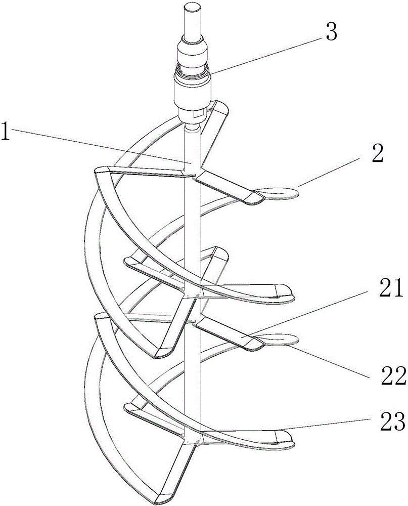
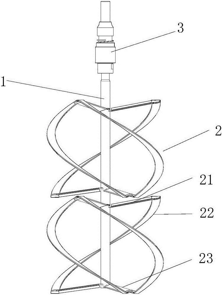
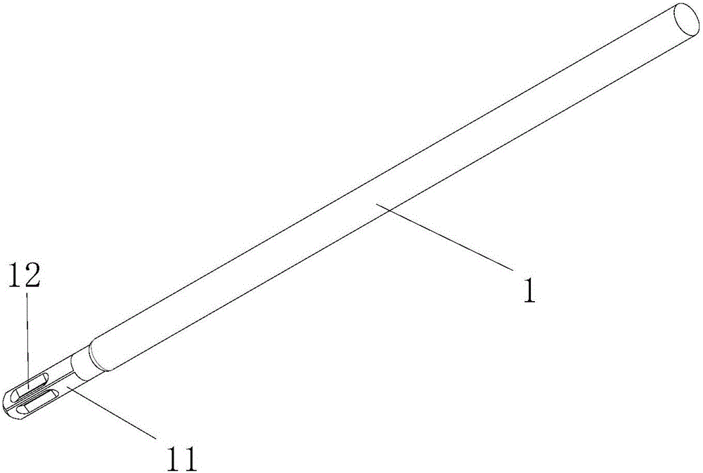
[0025] refer to figure 1 and figure 2 A stirring paddle in this embodiment includes a stirring shaft 1 , a paddle 2 and a connecting part 3 , the paddle 2 is welded to the stirring shaft 1 , and the connecting part 3 is arranged at the top of the stirring shaft 1 .

[0026] In the present embodiment, the blades 2 are two layers, and each layer of blades 2 is provided with three blades. The height of the blades is 152 mm, the maximum radius of the blades is 72 mm, and the width of the blades is 36 mm. The surface of the blades must not have scratches. refer to Figure 5 , the blades include an upper inner swirl plate 21, a lower inner swirl plate 23 and an outer swirl plate 22, one end of the...


PUM

PropertyMeasurementUnit
heightaaaaaaaaaa
radiusaaaaaaaaaa
widthaaaaaaaaaa

Abstract

The invention relates to a stirring paddle. The stirring paddle comprises a stirring shaft, paddle blades and a connecting component. The paddle blades and the stirring shaft are connected in a welding manner. The connecting component is arranged at the top end of the stirring shaft. The stirring paddle is characterized in that at least two layers of paddle blades are arranged, each layer of paddle blades at least comprise three blades, and each blade comprises an upper inner rotational flow plate, a lower inner rotational flow plate and an outer rotational flow plate, wherein one end of the upper inner rotational flow plate and one end of the lower inner rotational flow plate are welded to the stirring shaft, and the other end of the upper inner rotational flow plate and the other end of the lower inner rotational flow plate are connected to the two ends of the outer rotational flow plate in a welding manner; and the upper inner rotational flow plates, the lower inner rotational flow plates and the outer rotational flow plates are obliquely arranged relative to the horizontal plane, the upper inner rotational flow plates and the lower inner rotational flow plates incline downwards in the rotation direction of the stirring shaft, and the outer rotational flow plates incline upwards in the rotation direction of the stirring shaft. According to the stirring paddle, the purpose of improving the stirring effect is achieved by changing the inner rotational flow plates and the outer rotational flow plates of the stirring paddle blades, and therefore the weight and the size of the structure cannot be increased, and labor wasting and other adverse effects cannot be generated on cement stirring work.

Description

technical field [0001] The invention relates to a stirring paddle, in particular to a stirring paddle for stirring decoration materials. Background technique [0002] On small construction sites or decoration sites, cement concrete, glue (liquid), cement, putty powder, etc. are generally mixed manually, which is time-consuming and laborious, and it is difficult to control the mixing quality of the mixture. [0003] In view of the defects in the mixing operation of the above-mentioned decoration materials, some small mixers have appeared on the market to replace manual mixing of cement concrete, glue (liquid), mastic, putty powder, etc. The structure of the stirring paddle is the most important factor affecting the mixing effect of the mixer. Influencing factors, the most traditional mixer mainly welds a number of independent stirring blades on the stirring shaft. The stirring blades are similar to the structure of an electric fan, and they are all inclined in one direction. ...

Claims


Application Information

Patent Timeline
Patent Type & Authority Applications(China)
IPC IPC(8): B28C5/08
CPCB28C5/0806
Inventor 沈之珊冯嚞张一良
Owner HANGZHOU MINGPIN DECORATION ENG
Learn More