
A Connection Mechanism Adaptable to Cabin Deformation

A connecting mechanism and cabin technology, applied in motor vehicles, space navigation equipment, space navigation aircraft, etc., can solve the problems of main structure deformation of the cabin body, shorten the service life of the structure, deformation of the support structure, etc., and achieve simple composition Effect

Active Publication Date: 2018-03-20
BEIJING INST OF SPACECRAFT SYST ENG
View PDF5 Cites 0 Cited by
  • Summary
  • Abstract
  • Description
  • Claims
  • Application Information

AI Technical Summary

Problems solved by technology

The common in-cabin product connection structure requires high assembly accuracy, which needs to be ensured by combined processing or precise assembly methods. After launching into orbit with the sealed cabin, the main structure of the cabin will be damaged due to the pressure in the sealed cabin. There is a phenomenon of deformation under internal pressure, resulting in subsidiary deformation of the supporting structure installed on the main structure of the cabin
This subsidiary deformation will lead to difficulty in disassembly or even failure during on-orbit maintenance and disassembly of the support structure. At the same time, this subsidiary deformation will also cause long-term assembly stress in the support structure and reduce the service life of the structure.

Method used


Image

  • A Connection Mechanism Adaptable to Cabin Deformation
  • A Connection Mechanism Adaptable to Cabin Deformation
  • A Connection Mechanism Adaptable to Cabin Deformation

Examples


Embodiment Construction

[0023] The connection structure of the present invention is suitable for products with certain rigidity, but not for flexible products.

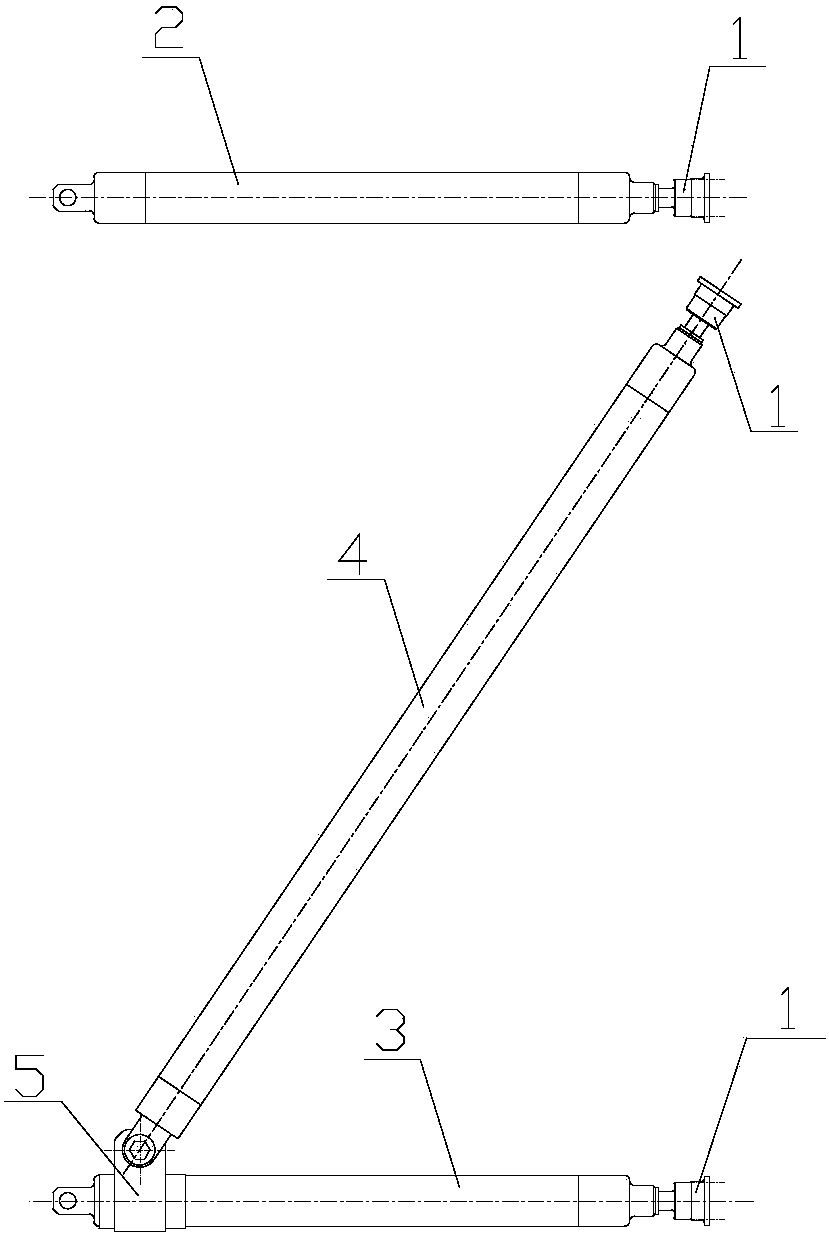
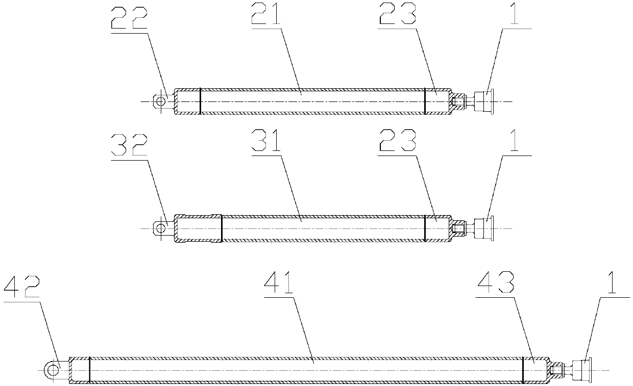
[0024] Such as figure 1 As shown, a connection mechanism that can adapt to the deformation of the cabin body, which includes: a spherical hinge 1, an upper end transverse bar assembly 2, a lower end transverse bar assembly 3, a tie rod assembly 4, a tie rod angle adjustment joint 5; the adaptable cabin body The deformed connection mechanism is Z-shaped as a whole, and the upper transverse bar assembly 2, the lower transverse bar assembly 3 and the tie bar assembly 4 all include: a bar, and connecting joints and adjustment joints located on both sides of the bar.

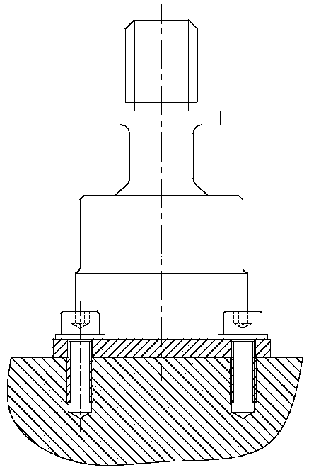
[0025] The number of spherical hinges 1 is 3, and there are 4 through holes on the base of the spherical hinges, which are connected with the method of threaded connection of the cabin structure. The top of the spherical hinges is a metal rod with external threads, showing the view...


PUM


Abstract

The invention discloses a connecting mechanism adaptable to cabin deformation. The connecting mechanism comprises an upper-end transverse rod piece assembly, a lower-end transverse rod piece assembly and a pull rod assembly. The integral layout of the connecting mechanism adaptable to cabin deformation in the space is in a Z shape. The upper-end transverse rod piece assembly, the lower-end transverse rod piece assembly and the pull rod assembly each comprise a rod piece, a connecting connector and an adjusting connector, and each connecting connector and each adjusting connector are located on the two sides of the corresponding rod piece. The connecting connector of the lower-end transverse rod piece assembly is provided with a limiting groove. The connecting connector of the pull rod assembly is provided with a through hole. The connecting connector of the pull rod assembly is connected with the end, close to the connecting connector of the lower-end transverse rod piece assembly, of the rod piece through a pull rod angle adjusting connector. The adjusting connector of the upper-end transverse rod piece assembly, the adjusting connector of the lower-end transverse rod piece assembly and the adjusting connector of the pull rod assembly are fixedly connected with spherical hinges correspondingly, and the three spherical hinges are all connected with a structure inside a cabin. The connecting connector of the upper-end transverse rod piece assembly and the connecting connector of the lower-end transverse rod piece assembly are movably connected with external products correspondingly.

Description

technical field [0001] The invention belongs to the technical field of aerospace assembly, and in particular relates to a connection mechanism capable of adapting to the deformation of a cabin body. Background technique [0002] With the development of my country's manned spaceflight industry, a support structure that can provide load installation, has sufficient mechanical properties to withstand the load of the launch section, and is convenient for on-orbit maintenance or disassembly is required inside the structure of the space station and other sealed cabins. The common in-cabin product connection structure requires high assembly accuracy, which needs to be ensured by combined processing or precise assembly methods. After launching into orbit with the sealed cabin, the main structure of the cabin will be damaged due to the pressure in the sealed cabin. There is a phenomenon of deformation under internal pressure, which leads to subsidiary deformation of the supporting st...

Claims


Application Information

Patent Timeline
Patent Type & Authority Patents(China)
IPC IPC(8): B64G1/22
CPCB64G1/22
Inventor 张啸雨李翔许焕宾梁东平张晓莉
Owner BEIJING INST OF SPACECRAFT SYST ENG
Learn More