Vacuum adsorption lifting appliance and use method thereof

A technology of vacuum adsorption and vacuum suction cups, which is applied in the direction of conveyor objects, transportation and packaging, etc., can solve problems such as damaged connections of cables and cable connectors, unstable adsorption of vacuum devices, and bruising of thin aluminum plates, etc., so as to reduce maintenance costs, Convenient and fast maintenance, reliable adsorption effect

Inactive Publication Date: 2016-09-21
GUIZHOU ALUMINUM MATERIALS ENG TECHRES CENT
View PDF16 Cites 3 Cited by
  • Summary
  • Abstract
  • Description
  • Claims
  • Application Information

AI Technical Summary

Problems solved by technology

[0002] In the thin aluminum plate production workshop, the thin aluminum plate (such as width 1m×length 2m) is often transported and processed by the crane. When the crane is used for suspension and transfer, the thin aluminum plate needs to be sucked and hung by the vacuum device attached to the driving hook. However, the existing vacuum device is unstable when adsorbed, and often swings, causing the thin aluminum plate to be damaged or deformed. In addition, the vacuum device needs to be connected to the cable, but when the existing cable is wound through the winder, the cable is due to the up and down of the hook. The movement is in a state of tension, which will lead to damage and unreliable connection of cables and cable connectors for a long time

Method used


Image

  • Vacuum adsorption lifting appliance and use method thereof
  • Vacuum adsorption lifting appliance and use method thereof
  • Vacuum adsorption lifting appliance and use method thereof

Examples


Embodiment 1

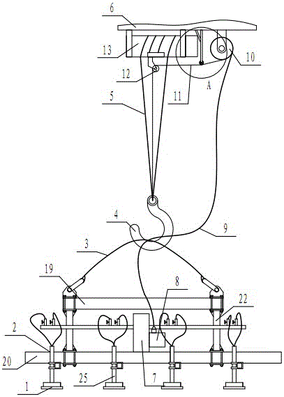
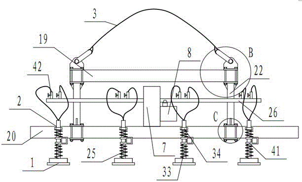
[0032] Embodiment 1: as Figure 1-Figure 7 As shown, a vacuum suction hanger includes a plurality of vacuum suction cups 1, and the plurality of vacuum suction cups 1 are symmetrically installed on a support frame 2 at intervals. 5 is connected on the walking box 6.

[0033] Preferably, each of the above-mentioned vacuum chucks 1 is connected to the vacuum device 7 through a pipeline, the vacuum device 7 is installed on the support frame 2, and the connected pipeline is a hose, which is connected in parallel to the output pipeline 26 of the vacuum device 7, and the output The pipeline 26 is fixedly connected to the middle part of the vertical connecting beam 22, and a valve 42 is installed on the pipeline connecting the output pipeline 26 to each section of the vacuum chuck 1.

[0034] Preferably, the above-mentioned vacuum device 7 includes a vacuum pump 8, the vacuum pump 8 is connected with the free end of the cable 9 for power supply or control, and the other end of the c...

Embodiment 2

[0043] Embodiment 2: a kind of use method of vacuum adsorption sling, the method comprises the following steps:

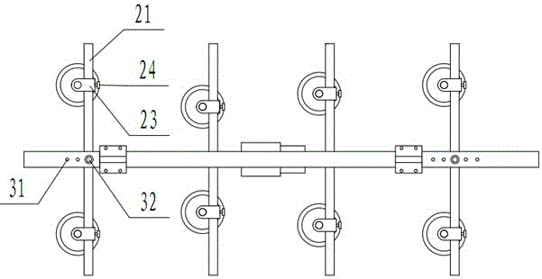
[0044] (1) The diameter of the vacuum suction cup is 280-330mm, and eight vacuum suction cups are set on the suction cup beam, with the attached beam as the center line, and four pairs of vacuum suction cups are arranged on both sides with symmetrical intervals;

[0045] (2) Adjust the bottom surfaces of the eight vacuum suction cups to keep the same surface, and the error of the same surface is 0.3-0.8mm;

[0046] (3) Adjust the vertical and horizontal distances of the eight vacuum suction cups, the distance between every two pairs of vacuum suction cups is equal, the distance is 480-520mm, the distance between each pair of vacuum suction cups is not equal, and the distance between each pair of vacuum suction cups from left to right is the width of the thin aluminum plate 0.8 times, 0.5 times, 0.65 times and 0.8 times;

[0047] (4) Connect eight vacuum suction cu...


PUM


Abstract

The invention discloses a vacuum adsorption lifting appliance and a use method thereof. The vacuum adsorption lifting appliance comprises a plurality of vacuum suckers which are symmetrically mounted on a supporting rack at intervals; the supporting rack is hooked onto a hook via a nylon tape; and the hook is connected onto a traveling case via a wire rope. As the vacuum suckers are symmetrically adsorbed onto a thin Al-plate at intervals, the adsorption of the thin Al-plate is more reliable, the moving process is stabler, the swinging possibility is low, and both surface scratching and large deformation of the thin Al-plate caused by touch can be avoided.

Description

technical field [0001] The invention relates to a vacuum adsorption hanger and a using method thereof, and belongs to the technical field of processing and conveying devices for thin aluminum plates. Background technique [0002] In the thin aluminum plate production workshop, the thin aluminum plate (such as width 1m×length 2m) is often transported and processed by the crane. When the crane is used for suspension and transfer, the thin aluminum plate needs to be sucked and hung by the vacuum device attached to the driving hook. However, the existing vacuum device is unstable when adsorbed, and often swings, causing the thin aluminum plate to be damaged or deformed. In addition, the vacuum device needs to be connected to the cable, but when the existing cable is wound through the winder, the cable is due to the up and down of the hook. The movement is in a state of tension, which will cause damage to the cables and cable connectors and unreliable connections for a long time....

Claims


Application Information

Patent Timeline
Patent Type & Authority Applications(China)
IPC IPC(8): B65G47/91
CPCB65G47/91
Inventor 车云门三泉张中可
Owner GUIZHOU ALUMINUM MATERIALS ENG TECHRES CENT
Why Eureka
Try Eureka