Elevator traction-bearing mechanism
A technology of elevator traction and bearing mechanism, which is applied to elevators, lifts, transportation and packaging in buildings, etc., which can solve the problems of high material cost, shortening, and high processing cost, so as to avoid excessive force and prolong service life , Reduce the effect of machining accuracy
- Summary
- Abstract
- Description
- Claims
- Application Information
AI Technical Summary
Problems solved by technology
Method used
Image

Examples
Embodiment 1
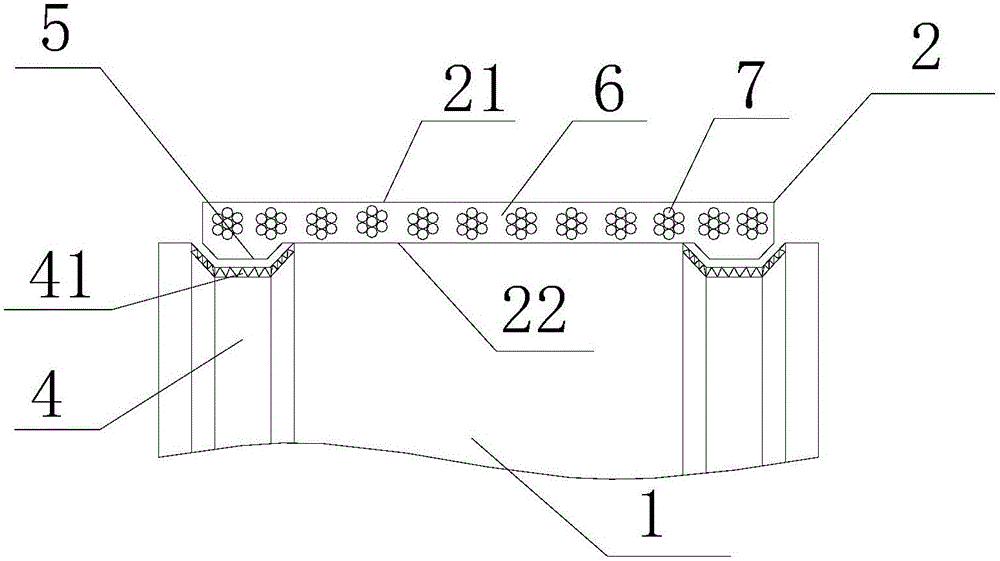
[0030] see figure 1 , an elevator traction bearing mechanism, including a traction bearing unit 2, a rotating wheel 1 matched with the traction bearing unit 2, the traction bearing unit 2 is used to carry and move the car, and part of the circumference of the rotating wheel 1 Wrapping, the traction bearing unit 2 is a flat belt and has a first working surface 21 and a second working surface 22, the first working surface 21 is a plane, and there is a protruding traction on both sides of the second working surface 22. Guide the protruding guide body 5 of the carrying unit 2; the rolling surface of the rotating wheel 1 has two matching grooves 4 that cooperate with the two protruding guide bodies 5. When each protruding guide body 5 cooperates with the corresponding matching groove 4 , there is a gap between the outer surface of the protruding guide body 5 and the inner surface of the matching groove 4 .
[0031] In this embodiment, the traction bearing unit 2 includes a load-be...
Embodiment 2
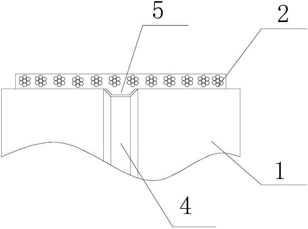
[0036] see figure 2 The difference between the present embodiment and the first embodiment is that: the second working surface 22 of the traction bearing unit 2 is only provided with a protruding guide body 5 in the middle position, and the rotating wheel 1 is only provided with the right one in the middle position. Cooperating with the groove 4, the surface area of a protruding guide body 5 is less than 30% of the area of the second working surface 22.
Embodiment 3
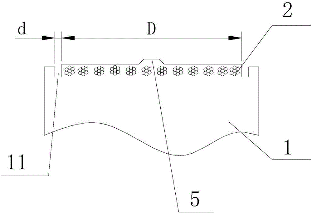
[0038] see image 3The difference between the present embodiment and the first embodiment is that the first working surface 21 of the traction bearing unit 2 cooperates with the rotating wheel 1, and the rotating wheel 1 has a concave traction wheel groove 11, and the traction wheel groove 11 is in contact with the rotating wheel 1. Cooperate with the first working surface 21 and have an axial clearance. In this embodiment, when the first working surface 21 fits in the middle of the traction wheel groove 11, there is an axial clearance d between the two sides of the traction bearing unit 2 and the traction sheave groove 11, and the axial clearance d The width is 1%-10% of the width D of the traction bearing unit 2 .
PUM
 Abstract
Description
Claims
Application Information
 - Generate Ideas
- Intellectual Property
- Life Sciences
- Materials
- Tech Scout
- Unparalleled Data Quality
- Higher Quality Content
- 60% Fewer Hallucinations
Browse by: Latest US Patents, China's latest patents, Technical Efficacy Thesaurus, Application Domain, Technology Topic, Popular Technical Reports.
© 2025 PatSnap. All rights reserved.Legal|Privacy policy|Modern Slavery Act Transparency Statement|Sitemap|About US| Contact US: help@patsnap.com