
PDC (polycrystalline diamond compact) bit vibration reduction and torque increase device

A drill bit and core tube technology, applied in the field of vibration reduction and torque increase devices, can solve the problems of strong stratum heterogeneity, slow drilling speed, and short service life of the drill bit, so as to improve the ability of cutting teeth to break rock and avoid cutting teeth damage, prolonging the service life

Inactive Publication Date: 2016-09-21
CHINA UNIV OF PETROLEUM (EAST CHINA)
View PDF5 Cites 3 Cited by
  • Summary
  • Abstract
  • Description
  • Claims
  • Application Information

AI Technical Summary

Problems solved by technology

However, the application effect of PDC bits in the above formations is poor, usually manifested in low drilling efficiency and short bit life
[0003] When the PDC bit drills in deep and complex formations, due to the poor drillability of the formation, it is more difficult for the cutting teeth to break the rock, the cutting efficiency is reduced, and the drilling speed is slow; at the same time, the formation is heterogeneous and the irregular vibration of the drill is significant, resulting Cutting teeth are prevented from premature failure, and the service life of the drill bit is short

Method used


Image

  • PDC (polycrystalline diamond compact) bit vibration reduction and torque increase device
  • PDC (polycrystalline diamond compact) bit vibration reduction and torque increase device
  • PDC (polycrystalline diamond compact) bit vibration reduction and torque increase device

Examples


Embodiment Construction

[0024] The specific implementation of the PDC drill bit vibration reduction and torsion increasing device of the present invention will be further described in detail below in conjunction with the accompanying drawings.

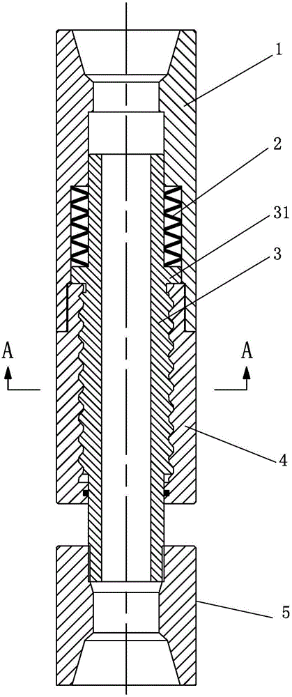
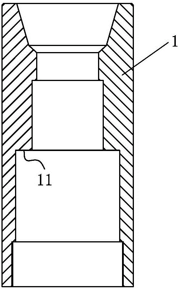
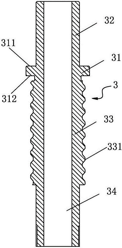
[0025] Such as figure 1 , figure 2 , image 3 and Figure 4 Commonly shown, the PDC drill bit vibration reduction and torsion increasing device of the embodiment of the present invention includes: a cylinder body having a cylinder inner cavity penetrating along its axial direction, and the cylinder body is formed by screwing the outer cylinder 4 and the upper joint 1 , the upper end of the upper joint 1 is provided with an upper joint thread for connecting with the drill string, the upper joint thread is a female thread, and a stepped surface 11 perpendicular to the axial direction is provided on the inner side of the lower part of the upper joint 1 . A core tube 3 is arranged in the inner cavity of the cylinder, and the core tube 3 has a core tube inner ...


PUM


Abstract

The invention discloses a PDC (polycrystalline diamond compact) bit vibration reduction and torque increase device. The PDC bit vibration reduction and torque increase device comprises a barrel formed by connection of an outer barrel and an upper joint, an annular retaining plate is arranged on the outer periphery of a core tube which is arranged in an inner cavity of the barrel body, and the lower surface of the annular retaining plate is supported on the upper end face of the outer barrel. A portion below the annular retaining plate is a lower core tube section in spiral spline connection with the outer barrel, and the lower end of the lower core tube section extends out of the outer barrel to be connected with a lower joint. A portion above the annular retaining plate is an upper core tube section, a Belleville spring is arranged in an annular space formed by the upper core tube section and the upper joint, the upper end of the spring is abutted against an inner step surface of the lower portion of the upper joint, and the lower end of the spring is abutted against the upper surface of the annular retaining plate. The PDC bit vibration reduction and torque increase device has advantages that flexible connection between a drill bit and a drill stem is realized, vibration generated in a drilling process of a PDC bit is weakened, damages of cutting teeth due to vibration are avoided, and the service life of the drill bit is prolonged; during spiral ascending of the drill bit, contact area of the cutting teeth and rock is reduced while cutting acting force is increased, and rock breaking performance of the drill bit is improved.

Description

technical field [0001] The invention relates to the technical field of oil and gas exploration equipment, in particular to a vibration reduction and torque increase device for downhole operation of a PDC drill bit. Background technique [0002] PDC bit is a kind of cutting type drill bit which uses artificial polycrystalline diamond compact as the rock-breaking element (PDC is the abbreviation of Polycrystalline Diamond Compact bit in English, and PDC bit is the abbreviation of polycrystalline diamond compact bit). The homogeneous formation has high drilling efficiency and service life, and is currently the main drill bit in the oil and gas drilling industry. With the continuous deepening of petroleum exploration and development, shallow and easy-to-develop oil and gas resources are decreasing year by year, and seeking oil and gas resources in deep and complex strata conditions has become an important task in oil and gas exploration and development. However, the application...

Claims


Application Information

Patent Timeline
IPC IPC(8): E21B12/00E21B12/04
CPCE21B12/00E21B12/04
Inventor 朱丽红黄勇邹德永王京印闫瑾申王志斌周玉刚
Owner CHINA UNIV OF PETROLEUM (EAST CHINA)
Learn More