A split-type plunger steel wire drainage device

A liquid drainage device, split technology, applied in the direction of wellbore/well valve device, production fluid, wellbore/well components, etc., can solve the problem of insufficient energy in the plunger well, and the inability of the plunger and effusion to be lifted to Wellhead and other problems to achieve the effect of ensuring service life, preventing twisting, and high drainage efficiency

Active Publication Date: 2018-09-04
BC P INC CHINA NAT PETROLEUM CORP +1
View PDF1 Cites 0 Cited by
  • Summary
  • Abstract
  • Description
  • Claims
  • Application Information

AI Technical Summary

Problems solved by technology

[0004] The purpose of the present invention is to solve the problem that the plunger is easily stuck during operation and the energy in the well is insufficient, so that the plunger and the accumulated fluid cannot be lifted to the wellhead

Method used


Image

  • A split-type plunger steel wire drainage device
  • A split-type plunger steel wire drainage device
  • A split-type plunger steel wire drainage device

Examples


Embodiment 1

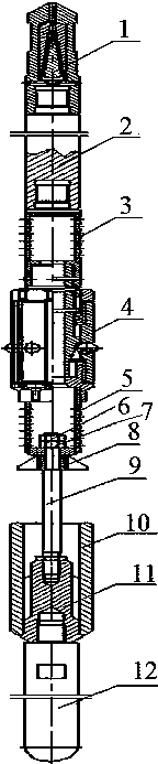
[0026] This embodiment provides a figure 1 The shown split plunger wire drainage device is divided into upper and lower parts. The upper part includes a wire rope connector 1, an upper weighting rod 2, an upper screen tube 3, a damper 4, The lower screen tube 5, the lower part includes a fin ring 8, a coupling rod 9, a plunger and a lower weighting rod 12, the upper end of the coupling rod 9 is connected to the lower screen tube 5 after passing through the fin ring 8, and the plunger includes a column The plug sleeve 10 and the plunger rod 11, the lower end of the plunger sleeve 10 is sealed after being connected with the lower end of the plunger rod 11, the lower end of the connecting rod 9 is inserted into the plunger sleeve 10 and connected to the upper end of the plunger rod 11, the column The lower end of the plug rod 11 is connected with the lower weighting rod 12 , the outer diameter of the plunger sleeve 10 is smaller than the inner diameter of the oil pipe, and the de...

Embodiment 2

[0035] On the basis of Embodiment 1, this embodiment provides a split-type plunger wire drainage device. The lower screen tube 5 is a metal cylinder with holes on the wall of the cylinder, and the lower end is fixedly connected with an external thread. The plug, the central position of the plug is provided with a circular hole, the upper end of the connecting rod 9 passes through the circular hole, and is connected with the lower screen tube 5 through the bearing nut 7 and the back cap 6, seefigure 1 .

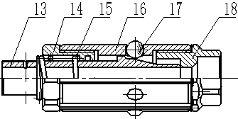
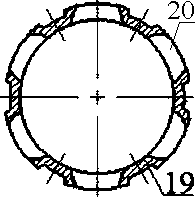
[0036] The connecting rod 9 is divided into two sections by a small upper shoulder and a large lower shoulder. The fin ring 8 is composed of three triangular metal plates evenly distributed on the outer wall of the cylinder and the cylinder. The fin ring 8 is sleeved on the connecting rod 9. The upper end is clamped between the lower end face of the lower screen tube 5 and the shoulder of the connecting rod 9 . See Figure 4 shown.

[0037] The outer diameter of the plunger ...


PUM


Abstract

The invention provides a split type plunger steel wire liquid draining device. The split type plunger steel wire liquid draining device is divided into an upper part and a lower part, wherein the upper part comprises a steel wire rope connector, an upper weighing rod, an upper sieve pipe, a damper and a lower sieve pipe which are sequentially in threaded connection from top to bottom; the lower part comprises a wing ring, a linkage rod, a plunger and a lower weighing rod, the upper end of the linkage rod penetrates through the wing ring and is connected with the lower sieve pipe, the plunger comprises a plunger sleeve and a plunger rod, the lower ends of the plunger sleeve and the plunger rod are connected and sealed, the lower end of the linkage rod is inserted into the plunger sleeve and is connected with the upper end of the plunger rod, the lower end of the plunger rod is connected with the lower weighing rod, the outer diameter of the plunger sleeve is smaller than the inner diameter of an oil tube, and the density of the plunger sleeve is smaller than that of the lower weighing rod. According to the split type plunger steel wire liquid draining device, the plunger is driven through a steel wire rope, so that a user does not need to be consider whether the energy in a well is sufficient, and the plunger is unlikely to be blocked; by virtue of the damper, the phenomena of twisting and bending of the steel wire rope caused by the upward movement accelerated by relatively high pressure in the well are effectively prevented, and the service life of the steel wire rope is guaranteed; the liquid draining efficiency is high, and accumulated liquid at the bottom of the well can be thoroughly eliminated.

Description

technical field [0001] The invention belongs to the technical field of natural gas well drainage and gas production, and in particular relates to a split plunger steel wire drainage device. Background technique [0002] Plunger drainage has attracted attention due to its simple process, easy installation and maintenance, and effective utilization of formation energy for drainage and production. All scientific research units are actively developing it. The "separate plunger sleeve without base" developed by Changqing Underground Operation Company in 2015, the patent number is: CN 205089591 U. The split plunger sleeve is mainly composed of a plunger body and a plunger sleeve. Through the control of the stroke and running time, they meet in the downhole and merge into one, forming a gas-liquid separation interface, and then open the wellhead to release the natural gas pressure in the well. Due to the pressure difference between the two ends, the plunger moves up, and the liqui...

Claims


Application Information

Patent Timeline
Patent Type & Authority Patents(China)
IPC IPC(8): E21B43/08E21B34/14
CPCE21B34/14E21B43/08
Inventor 邓继学刘培润焦峥辉韩静静景志明费节高吕希祥
Owner BC P INC CHINA NAT PETROLEUM CORP
Why Eureka
Try Eureka