fan

A technology of fan and air inlet ring, which is applied in the direction of mechanical equipment, machine/engine, liquid fuel engine, etc. It can solve the problems of ineffective collection, affecting the cleaning of the fan and the external environment, and affecting the filtering effect of the fan, so as to achieve a good oil filtering effect , keep clean effect

Active Publication Date: 2018-11-02
宁波日进环境科技有限公司
View PDF10 Cites 0 Cited by
  • Summary
  • Abstract
  • Description
  • Claims
  • Application Information

AI Technical Summary

Problems solved by technology

[0003] In addition, in order to improve the filtering effect of the fan, many existing fans are equipped with a filter disc at the air inlet, and the filter disc can rotate synchronously with the impeller. There is a gap between them, so that the wind outside the fan enters the inside of the fan through the gap, because this part of the wind is not filtered by the filter disc, which affects the filtering effect of the fan
In addition, during the working process of the existing fan, the oil droplets in the oil filter pan are directly thrown out of the fan under the action of centrifugal force, and cannot be collected effectively, thus affecting the cleaning of the fan and the external environment.

Method used


Image

  • fan
  • fan
  • fan

Examples


Embodiment 1

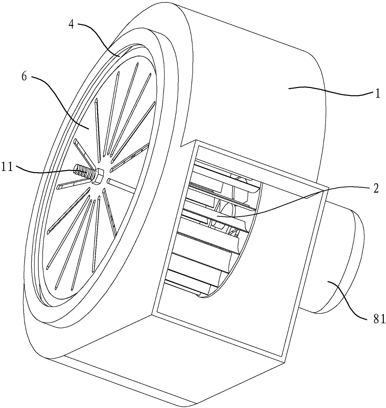
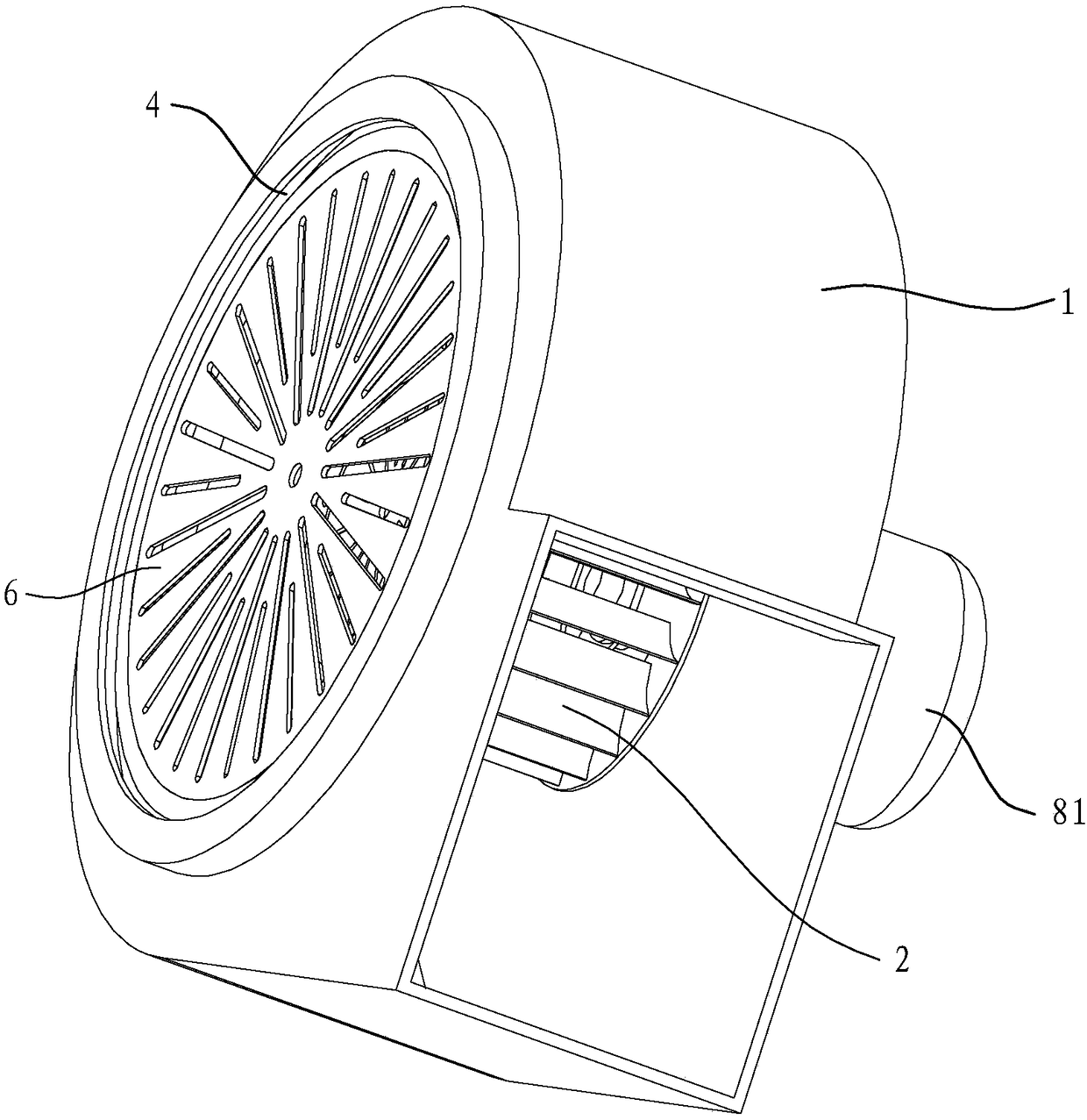
[0021] like figure 1 and figure 2 As shown, the fan in this embodiment includes a volute 1, an impeller 2 and an air inlet ring 3, the impeller 2 is installed inside the volute 1, the fan has an air inlet 10, and the air inlet ring 3 is located at the air inlet 10 In addition, the air inlet ring 3 is installed on the impeller 2 and can rotate synchronously with the impeller. There is a gap between the outer periphery of the air inlet ring 3 and the corresponding side wall of the volute 1. An oil filter pan that can rotate synchronously with the air intake ring. A first driving motor 81 is installed on the outer wall of the volute opposite to the air inlet ring 3 , and the impeller 2 is installed on the driving shaft of the first driving motor 81 .

[0022] In this embodiment, an oil receiving groove 4 is provided on the side wall of the volute 1 corresponding to the air inlet ring 3, and the oil receiving groove 4 is arranged around the air inlet 10 of the fan and has a rad...

Embodiment 2

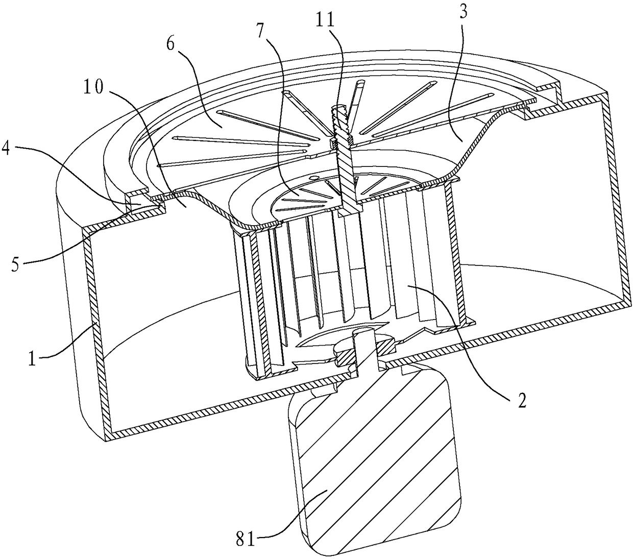
[0026] like image 3 and Figure 4 As shown, the outer oil filter pan 6 in the fan in this embodiment is fixed on the outer peripheral edge of the air inlet ring 3, the inner oil filter pan 7 is fixed on the inner peripheral edge of the air inlet ring 3, and the outer oil filter pan 6 and the inner side The oil filter pans 7 are not connected by a connecting shaft 11, and the rest of the structure is the same as that in Embodiment 1, and will not be further described here.

Embodiment 3

[0028] like Figure 5 As shown, the fan in this embodiment has two air inlets 10 arranged opposite to each other in the axial direction, and there are two air inlet rings 3, each air inlet ring 3 is arranged on the air inlet 10 on the corresponding side, and a drive is installed inside the fan The second drive motor 82 for the rotation of the impeller 2, and the two air inlet rings 3 are installed on the impeller 2 and can rotate synchronously with the impeller. In addition, fixed brackets 9 are installed on both outer walls of the volute 1 , and the drive shaft of the second drive motor 82 passes through the corresponding side of the air inlet ring 3 and is rotatably mounted on the corresponding side of the fixed brackets 9 .


PUM


Abstract

The invention discloses a draught fan. The draught fan comprises a volute and an impeller arranged in the volute. An air inlet ring is arranged at an air inlet of the draught fan. The draught fan is characterized in that the air inlet ring is arranged on the impeller and can synchronously rotate along with the impeller, and a gap is reserved between the peripheral edge of the air inlet ring and the corresponding side wall of the volute. The air inlet ring is provided with the oil filtering disc synchronously rotating with the air inlet ring. Compared with the prior art, the draught fan has the beneficial effects that due to the fact that the air inlet ring of the draught fan can synchronously rotate along with the impeller and the oil filtering disc installed on the air inlet ring can synchronously rotate along with the air inlet ring, the draught fan overcomes the defect that a gap exists between an oil filtering disc and an air inlet ring of an existing draught fan, the situation that wind on the outer side of the air inlet is not filtered by the oil filtering disc and directly enters the draught fan is avoided, and accordingly the draught fan can have a better oil filtering effect. In addition, oil drops on the oil filtering disc can be thrown out through centrifugal force generated during high-speed rotation of the air inlet ring, and therefore cleanliness of the oil filtering disc is easily kept.

Description

technical field [0001] The invention relates to a ventilation device, in particular to a fan. Background technique [0002] Existing fans all include a volute and an impeller. The impeller is installed inside the volute and rotates under the drive of the drive motor. An air inlet ring is installed at the air inlet of the fan, and the air inlet ring is fixed on the volute. Similar fan structures can refer to the following patents: "Range Hood Fan and Range Hood" as disclosed in the Chinese invention patent No. ZL 201110275861.7 (authorized announcement No. CN 102287402B). [0003] In addition, in order to improve the filtering effect of the fan, many existing fans are equipped with a filter disc at the air inlet, and the filter disc can rotate synchronously with the impeller. There is a gap between them, so that the wind outside the fan enters the inside of the fan through the gap. Since this part of the wind is not filtered by the filter disc, the filtering effect of the fa...

Claims


Application Information

Patent Timeline
Patent Type & Authority Patents(China)
IPC IPC(8): F04D29/70F04D29/62
CPCF04D29/626F04D29/703
Inventor 董贵生
Owner 宁波日进环境科技有限公司
Why Eureka
Try Eureka