Dual-way thermodynamic cycle and first-type thermal-drive compression heat pump

A compression heat pump and thermodynamic cycle technology, applied in irreversible cycle compressors, compressors, fluid circulation arrangements, etc., can solve problems such as inability to convert heat energy, limitation of application fields and scope of application, and difficulty in realizing efficient utilization of heat energy.

Active Publication Date: 2016-09-21
李华玉
View PDF17 Cites 17 Cited by
  • Summary
  • Abstract
  • Description
  • Claims
  • Application Information

AI Technical Summary

Problems solved by technology

[0003] Thermal energy (temperature difference) utilization technology represented by absorption heat pump technology utilizes high temperature heat load to drive heat supply or cooling; big limit
Compression heat pump technology that utilizes the grade difference between mechanical en

Method used


Image

  • Dual-way thermodynamic cycle and first-type thermal-drive compression heat pump
  • Dual-way thermodynamic cycle and first-type thermal-drive compression heat pump
  • Dual-way thermodynamic cycle and first-type thermal-drive compression heat pump

Examples


Embodiment Construction

[0064] The first thing to explain is that in the expression of the structure and process, it will not be repeated if it is not necessary; the obvious process will not be expressed. The present invention will be described in detail below in conjunction with the accompanying drawings and examples.

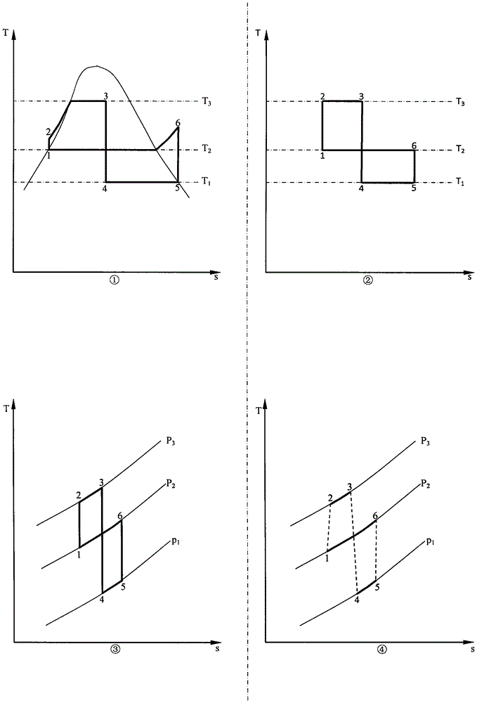
[0065] figure 1 The examples of the two-way thermodynamic cycle process in the T-s diagram shown are as follows:

[0066] Example ①, consisting of reversible adiabatic compression process 12, constant pressure endothermic process 23, reversible adiabatic expansion process 34, constant temperature endothermic process 45, reversible adiabatic compression process 56, constant pressure exothermic process 61, a total of 6 sequential processes process composition.

[0067] Example ②, consists of 12 reversible adiabatic compression process, 23 constant temperature endothermic process, 34 reversible adiabatic expansion process, 45 constant temperature endothermic process, 56 reversible adi...


PUM


Abstract

The invention provides a dual-way thermodynamic cycle and a first-type thermal-drive compression heat pump and belongs to the technical field of dynamics, refrigeration and heat pumps. The dual-way thermodynamic cycle 1234561 is composed of a course 12 in which a working medium is boosted from a middle temperature, a course 23 in which the working medium absorbs heat from a high-temperature heat source, a course 34 in which the working medium is decompressed from a high temperature, a course 45 in which the working medium absorbs heat from a low-temperature heat source, a course 56 in which the working medium is boosted from a low temperature, and a course 61 in which the working medium releases heat to a middle-temperature heat source. A compressor is equipped with a circulating medium channel which communicates with a second compressor by a heat supply device; the second compressor is equipped with a circulating medium channel which communicates with an expansion machine via a high-temperature heat exchanger; the expansion machine is equipped with a circulating medium channel which communicates with the compressor via a low-temperature heat exchanger; the high-temperature heat exchange is equipped with a high-temperature thermal medium pipeline which communicates with the external environment; the low-temperature heat exchange is equipped with a low-temperature thermal medium pipeline which communicates with the external environment; the heat supply device is equipped with a heated medium pipeline which communicates with the external environment; and the expansion machine is connected to the compressor and the second compressor and transmits power. In this way, the first-type thermal-drive compression heat pump is formed.

Description

Technical field: [0001] The invention belongs to the technical field of power, refrigeration and heat pump. Background technique: [0002] Cold demand, heat demand and power demand are common in human life and production; in reality, people often need to use high-temperature heat energy to achieve cooling, heating or conversion into power, and also need to use power for cooling or use power combined Low temperature thermal energy for heating. In the process of achieving the above goals, there will be many considerations or constraints, including the type, grade and quantity of energy, the type, grade and quantity of user needs, ambient temperature, type of working medium, equipment flow, structure and Manufacturing costs and more. [0003] Thermal energy (temperature difference) utilization technology represented by absorption heat pump technology utilizes high temperature heat load to drive heat supply or cooling; big limit. Compression heat pump technology, which utili...

Claims


Application Information

Patent Timeline
IPC IPC(8): F25B9/06F25B1/10F25B41/00F25B41/30F25B41/40
CPCF25B1/10F25B9/06F25B41/00
Inventor 李华玉
Owner 李华玉
Why Eureka
Try Eureka