
Solar concentration plant for the production of superheated steam

a solar energy and concentration plant technology, applied in steam generation plants, solar heat generation, lighting and heating apparatus, etc., can solve the problems of difficult solar technology for the production of superheated steam, affecting the operation of the system, and destroying practically all its potential for work

Inactive Publication Date: 2008-12-11
ABENGOA SOLAR NEW TECH SA
View PDF0 Cites 41 Cited by
  • Summary
  • Abstract
  • Description
  • Claims
  • Application Information

AI Technical Summary

Benefits of technology

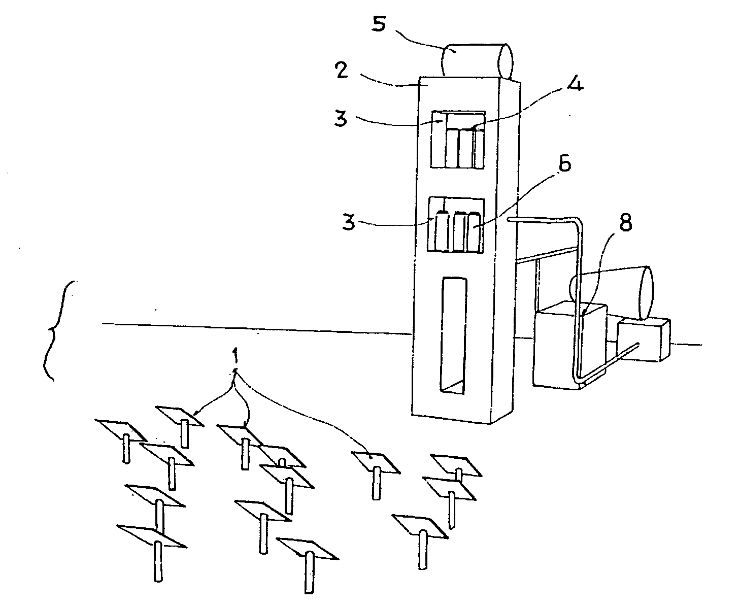
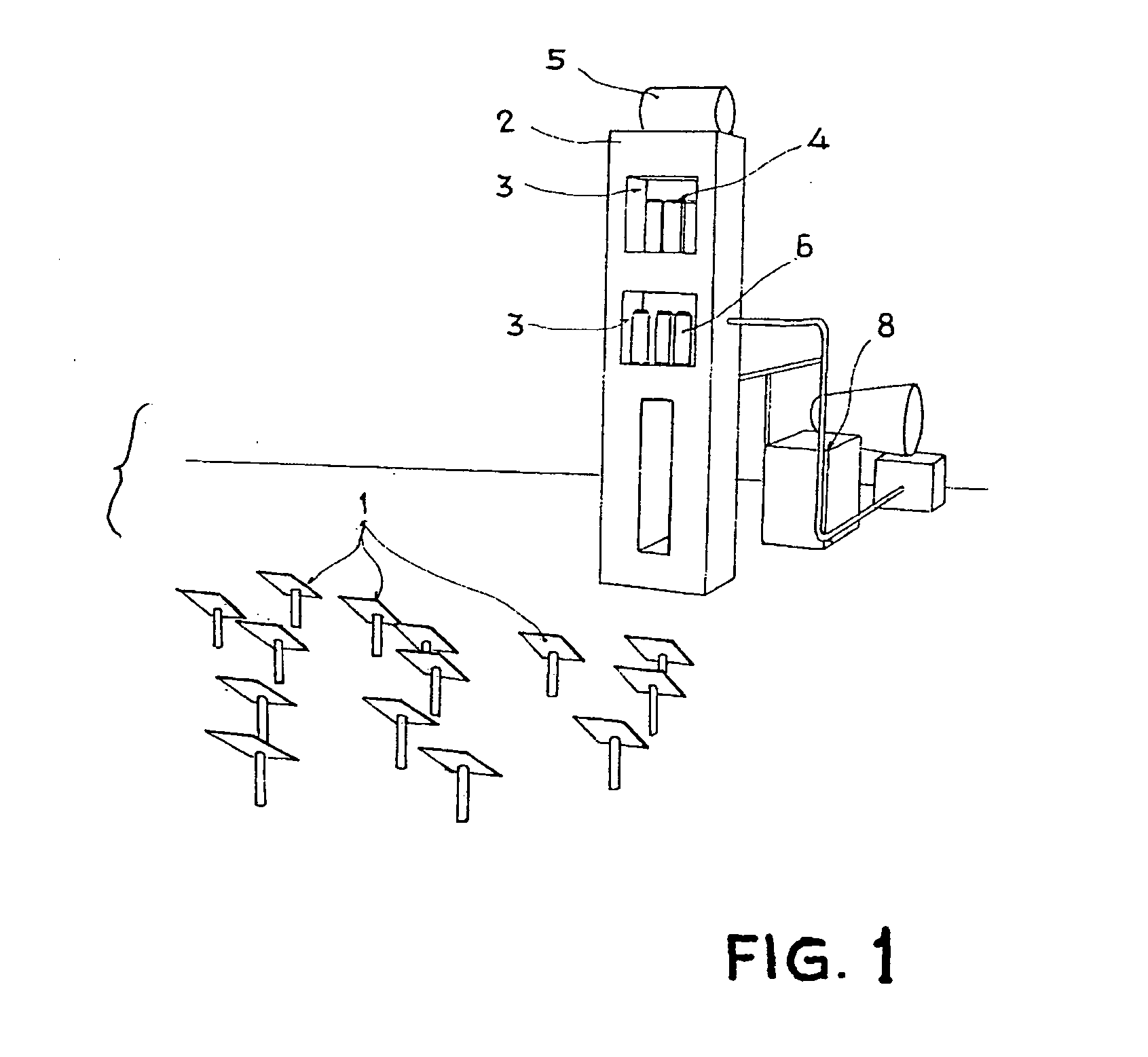
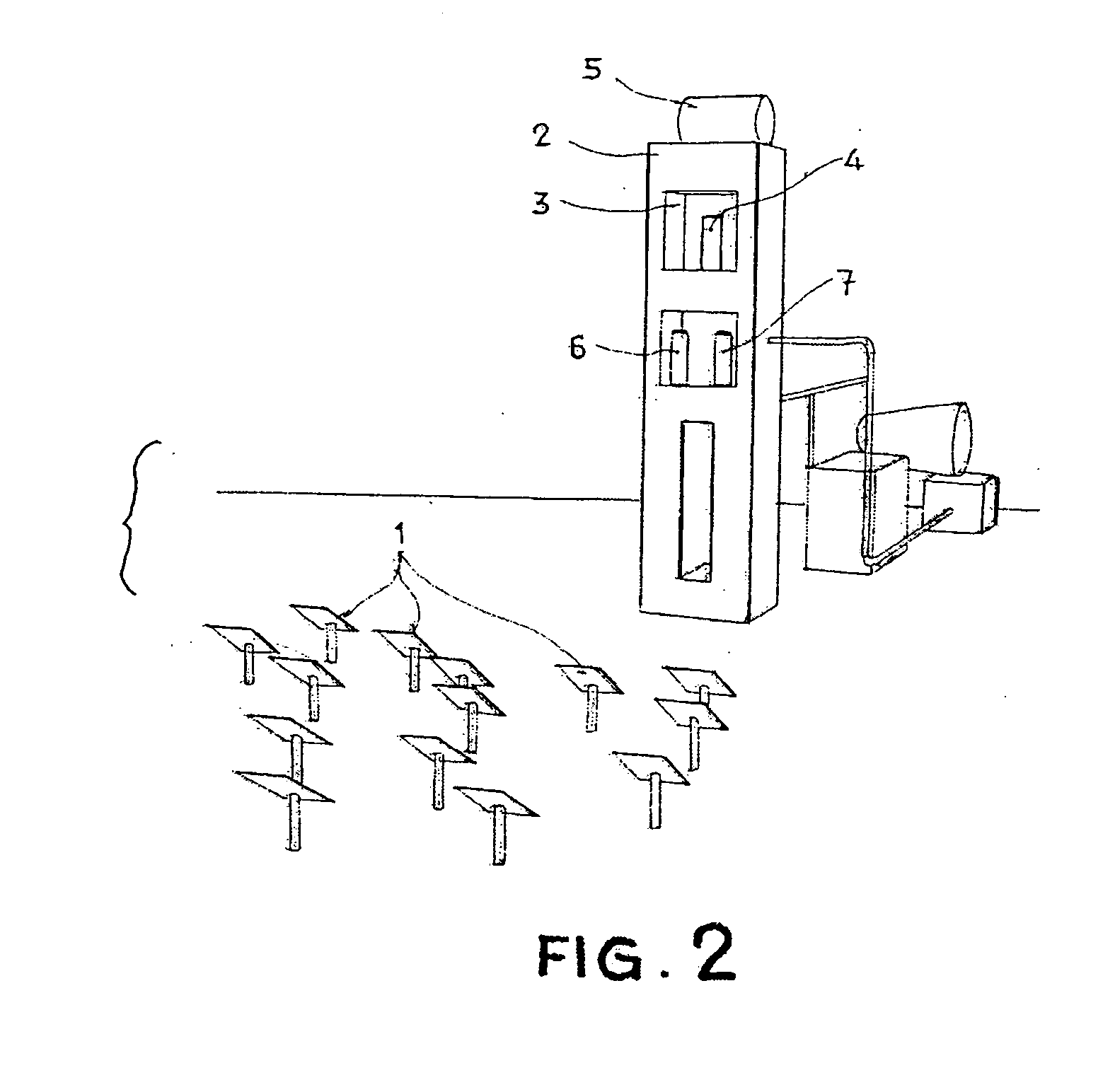
[0016]The fact of separating the evaporation stage from that of superheating reduces the technological risk as, due to there not being a change of phase in the receiver itself, neither are there any problems of high thermal gradients derived from the different film coefficients of both phases. In addition to physically and independently separating the evaporator and the superheater by means of the inclusion of an intermediate drum, this incorporates the carrying out of a strategic control of the pointing of the heliostat field which is independent for both receiving subsystems, the evaporator subsystem and the superheater subsystem. This strategic control consists of a dynamic control, capable of adapting the heliostat field, in order that after the provision of energy, optimal conditions of heat and pressure for entry into the turbine are maintained stable. To do this, the heliostat field is pointed towards one receiver or the other (evaporator or superheater) depending on the current need. By this it should be understood that there is a possibility of carrying out the pointing of individual heliostats or groups of the same, towards either the evaporator receiver or the superheater receiver, in such a way that they control jointly both the pressure in the drum and the superheater outlet temperature. In this way, part of the heliostat field will be directed towards the evaporator and the other part towards the superheater, thus achieving greater control over the plant and greater stability of the same.
[0017]In central receiver technology, the receiver is located at the top of the tower, and the heliostats concentrate the solar energy onto the same. The energy exchange occurs in the receiver, transferring the photonic energy of the concentrated beam of light coming from the field of heliostats to a heat-carrying fluid, increasing its enthalpy. There are many different ways of classifying the receivers. If we classify the receivers in accordance with their geometry, we may define the “cavity” type receivers as those which are located at the top of the tower within a hollow or cavity; in this way, the thermal losses due to radiation or convection are minimised. The receivers may be constituted in different ways, the most common for the direct generation of steam in central receiver systems being tubular solar panels.
[0024]These may include between the primary superheater and the secondary or final superheater a series of attemperators or an attemperation system, thus achieving a more precise control over the pressure- and temperature-related conditions of the superheated steam at the outlet of the superheater receiver.

Problems solved by technology

While solar radiation is a source of thermal energy of a high temperature at its origin, the use of the same under the conditions of the flow which reaches the surface of the earth destroys practically all its potential for conversion into work due to the drastic reduction in the temperature available in the flow.
The difficulty of solar technology for the production of superheated steam lies in the demanding conditions of temperature at which the receiver must operate.
The difficulties encountered in the experiments carried out on superheated steam receivers in the eighties were centred on two main aspects:A lack of controllability of the system, especially when faced with transitional conditions, the passing of clouds, etc., due mainly to the bad thermal properties of the superheated steam.
In both receivers, the most frequent structural fault was the appearance of cracks.
The thermal tension due to the great differences in temperature brought about the appearance of cracks in the interstitial weld between subpanels.

Method used


Image

  • Solar concentration plant for the production of superheated steam
  • Solar concentration plant for the production of superheated steam
  • Solar concentration plant for the production of superheated steam

Examples


Embodiment Construction

[0015]The present invention relates to a plant and a procedure which uses water / steam as a heat-carrying fluid for the production of superheated steam in any thermodynamic cycle or process heat exploitation system, comprised of an evaporation subsystem where saturated steam is produced under the conditions of pressure of the system, and a superheater subsystem where the steam reaches the required conditions of pressure and temperature for entry into the turbine. With regard to other preceding proposals which located the superheater subsystem modules in the very close proximity of (when not superimposed on) the evaporator subsystem modules, the strategic development proposed herein is based on the physical and independent separation of the evaporator and the superheater.

[0016]The fact of separating the evaporation stage from that of superheating reduces the technological risk as, due to there not being a change of phase in the receiver itself, neither are there any problems of high t...


PUM


Abstract

A solar concentration plant which uses water / steam as a heat-carrying fluid, in any thermodynamic cycle or system for the exploitation of process heat, which is comprised of an evaporation subsystem, where saturated steam is produced under the conditions of pressure of the system, and a superheater subsystem through which the steam reaches the required conditions of pressure and temperature at the turbine inlet, and in which an attemperation system (10) may be incorporated, these being physically separated and interconnected by means of a drum (5) in which the separation of water and steam takes place, and in which a strategic control of the pointing of the field of heliostats (1) towards either of the subsystems (evaporator or superheater) may be carried out, with individual or group pointing of the heliostats, in such a way that they jointly control both the pressure within the drum (5) and the outlet temperature of the superheated steam (11).

Description

[0001]The present invention relates to solar concentration plants with a physical separation between the evaporator and the superheater and with a dynamic control capable of adapting the heliostat field, in order to produce superheated steam in a controlled, efficient manner, in order to thus assure the continued durability and normal operation of said solar plant in its different applications: the production of electricity, the production of process heat, the production of solar fuels and their application to thermochemical processes.BACKGROUND OF THE INVENTION.[0002]While solar radiation is a source of thermal energy of a high temperature at its origin, the use of the same under the conditions of the flow which reaches the surface of the earth destroys practically all its potential for conversion into work due to the drastic reduction in the temperature available in the flow. For this reason, thermoelectric solar plants and optical concentration systems are used, which achieve a g...

Claims


Application Information

Patent Timeline
IPC IPC(8): F22B3/08F24S50/20
CPCF03G6/02F03G6/06F22B1/006F22G5/12F24J2/07Y02E10/41Y02E10/46F24S20/20Y02E10/40F03G6/063
Inventor GONZALEZ, MARCELINO SANCHEZGONZALEZ-AGUILAR, RAFAEL OSUNAQUERO, VALERIO FERNANDEZGILABERTE, RAUL NAVIO
Owner ABENGOA SOLAR NEW TECH SA
Learn More