High efficiency positive displacement thermodynamic system

a positive displacement, high-efficiency technology, applied in combination engines, machines/engines, mechanical equipment, etc., can solve the problems of insufficient condition to produce potential work loss, and insufficient mechanical conditions to achieve the expected efficiency increase, so as to minimize mechanical work, maximize the extraction effect, and minimize the amount of mechanical work

Active Publication Date: 2010-03-04
STAFFEND GILBERT
View PDF10 Cites 38 Cited by
  • Summary
  • Abstract
  • Description
  • Claims
  • Application Information

AI Technical Summary

Benefits of technology

[0036]A method is provided for moving a working fluid through a controlled thermodynamic cycle in a positive displacement fluid-handling device in such a manner that heat is moved with a minimal theoretical application of work (in the case of a refrigerator), or that the maximum theoretical amount of work is extracted from a given movement of heat (in the case of a heat engine). As used here, the terms minimum / maximum refer to the ability of the device to extract all of the mechanical energy invested into the working fluid, save frictional and / or heat losses consistent with the second law of thermodynamics. This method provides a working fluid at an inlet pressure. The working fluid comprises a compressible substance capable of intermittently storing and releasing mechanical energy. At least one compression chamber and one expansion chamber are provided. Each chamber has a respective displacement volume (swept volume) and a definable volumetric efficiency. A fixed quantity of working fluid is volumetrically compressed in the compression chamber, and similarly a fixed quantity of working fluid in the expansion chamber is volumetrically expanded. The pressure differential is created in the working fluid relative to the inlet pressure during one of the compressing and expanding steps. Following this, a variable amount of heat is moved into or out of the working fluid. Working fluid is returned to inlet pressure during the other one of the compressing and expanding steps entirely within the respective compression or expansion chamber. The step of returning working fluid to inlet pressure includes adjusting the expansion chamber's displacement volume relative to that of the compression chamber, based on well known thermodynamic relationships which depend on the compression ratio and heat exchange prior to entering the expander section. This step occurs without decreasing the volumetric efficiency of the compression and expansion chambers.
[0037]The subject method, when operated within the context of a positive displacement fluid-handling device, results in a highly efficient thermodynamic system. When the invention is implemented as a refrigerator, heat is moved by a minimum theoretical application of work. When implemented within a power cycle, this invention results in the production of a maximum of theoretical work from a given amount of heat in expansion. And even more specifically, when the power cycle implementation includes combustion, this invention produces a maximum of theoretical heat from a regulated combustion input pressure, quantity of fuel, and burning time in order to meet the guaranteed repeatability constraints of both heat produced and combustion byproducts. In other words, the method and device of this invention is readily adaptable to a refrigeration system or a heat engine. If the device is operated as a refrigeration system, it minimizes work input. If the method and device are operated as a heat engine, it maximizes work output.
[0039]The rotating valve plate arrangement of this device represents one alternative embodiment which enables the device to maintain a precise adjustment of required continuously varying asymmetric ratios between volumetric compression and expansion in order to exactly minimize the amount of mechanical work needed to move the target quantity of heat absorbed and released by the working fluid.
[0040]In refrigeration mode, the subject method and device helps to minimize the work required to move the heat. In power mode, the devices help to maximize the work extracted from the given input heat. Said another way, this method, as enabled through its various disclosed and exemplary embodiments, increases the coefficient of performance for refrigeration systems, and increases the thermal efficiency of heat engines. For combustion applications enabled by precise control capability, fuel may be burned in a chosen optimum manner, such as to discharge the most heat with a minimum of noxious byproducts. Advantageously, the capability for on-the-fly re-adjustment of the relationship between compression and expansion provides for the establishment of independent pressure targets without sacrificing volumetric efficiency resulting in maximum benefit with a minimum of energy expended.

Problems solved by technology

This creates a negative pressure in the cylinder relative to the outside air and results in a charge of fresh air being pulled into the chamber.
This necessary condition is not sufficient to produce the expected efficiency increase without many other conditions being met.
This means that potential work is lost when the exhaust valve is open, as far as 45 degrees before Bottom Dead Center.
Returning to the “throttling” distinction between spark- and compression-ignitions engines, when an engine is throttled down from wide open throttle to the maximum speed allowed on superhighways, the pumping loss increases thereby reducing engine efficiency.
Pumping losses increase dramatically beyond those shown for the common speeds of city driving.
Standard analytical practices fail to measure lost thermal potential except to take note of reduced mechanical efficiency, another average which has been carved away from shaft angle.
Excluding parasitic loads and friction, high speed mechanical efficiencies drop to substantially due primarily to losses described above.
Unfortunately, it also results in a portion of the compression-stroke being wasted or going unused, thereby under utilizing the compressor volume and contributing to inefficiencies such as friction and heat loss.
The largest penalty associated with the wasted compression stroke is the corresponding reduction in the mass of air inducted to the engine.
Atkinson cycle engines are known for good thermal efficiency but relatively poor power-to-volume and power-to-weight ratios.
While this gain in work does improve the overall thermodynamic efficiency of the engine, the reduced compression volume in these engines tends to reduce the relative power output of the engine, as previously described.
Therefore, current Atkinson cycle approaches have failed to achieve full thermodynamic benefits.
Compression ignition engines suffer from the same waste of mechanical energy when the exhaust valve opens before the combustion gases are expanded completely to atmospheric pressure.
As with attempts to achieve this gain in spark ignition engines, as in FIG. 1D, attempts to capture this theoretical gain in both diesel and dual-cycle thermodynamic systems have been impractical or incomplete.
An inherently efficient gas turbine stands in contrast to the inherently inefficient positive displacement heat engines described above.
However, turbine-based thermodynamic systems are not well suited to low speed and highly variable operating conditions.
As a result, turbine-based thermodynamic systems and engines are not typically used for automotive transportation and other such systems in which variable loads are common.
Just as heat engines implemented through positive displacement compressor-expander devices are plagued by low-efficiency issues, refrigeration systems face similar problems.
However, while these benefits have been theoretically forecast, practical units have not been constructed due to the difficulty of design and construction, and with the constraints of providing a low-cost energy recovery device that is sufficiently reliable.
Furthermore, constraints of high volume throughput and steady state operation also limit applications for this technology to certain, very specified and limited settings only.
Present turbine-based systems are not practically suited to achieve this type of highly efficient operation.

Method used


Image

  • High efficiency positive displacement thermodynamic system
  • High efficiency positive displacement thermodynamic system
  • High efficiency positive displacement thermodynamic system

Examples


Embodiment Construction

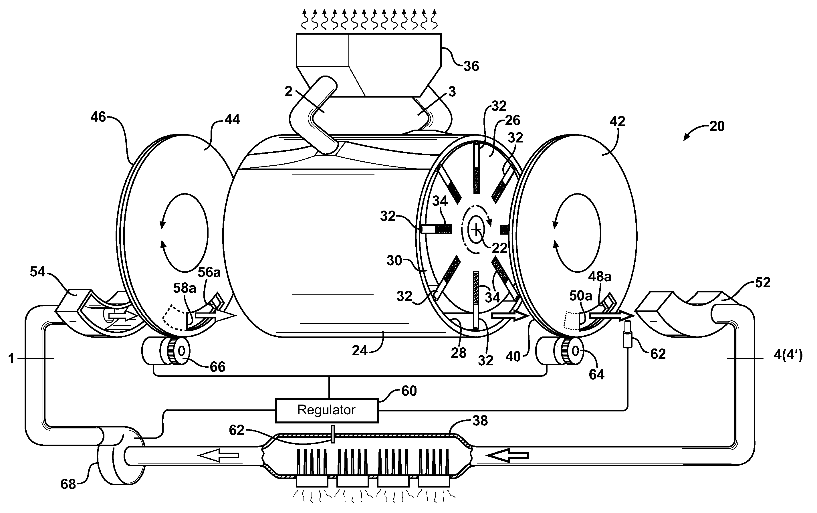
[0061]Referring to the Figures, wherein like numerals indicate like or corresponding parts throughout the several views, a positive displacement fluid-handling device, according to one embodiment of this invention, is generally shown at 20 in FIG. 6. In the embodiment depicted here, the device 20 takes the form of a rotary style positive displacement compressor / expander having an axis of rotation 22 oriented generally horizontal as viewed from FIG. 6. An outer stator portion 24 surrounds an internal rotor 26 supported for rotation about the axis 22. In this configuration, the stator 24 is static and the rotor 26 rotates with respect to the stator 24. The space between the inner wall 28 of the stator 24 and the outer surface 30 of the rotor 26 defines multiple working chambers which, as will be described in greater detail subsequently, form respective compression and expansion chambers. Extendible vanes 32 are supported in the rotor 26 and project outward into sliding contact against...


PUM


Abstract

Devices and methods for moving a working fluid through a controlled thermodynamic cycle in a positive displacement fluid-handling device (20, 20′, 20″) with minimal energy input include continuously varying the relative compression and expansion ratios of the working fluid in respective compressor and expander sections without diminishing volumetric efficiency. In one embodiment, a rotating valve plate arrangement (40, 42, 44, 46) is provided with moveable apertures or windows (48, 50, 56, 58) for conducting the passage of the working fluid in a manner which enables on-the-fly management of the thermodynamic efficiency of the device (20) under varying conditions in order to maximize the amount of mechanical work needed to move the target quantity of heat absorbed and released by the working fluid. When operated in refrigeration modes, the work required to move the heat is minimized. In power modes, the work extracted for the given input heat is maximized.

Description

CROSS REFERENCE TO RELATED APPLICATIONS[0001]This application is a continuation-in-part of U.S. application Ser. No. 11 / 532,366 filed Sep. 15, 2006, which claims the benefit of U.S. Provisional Patent Application Ser. No. 60 / 718,029 filed Sep. 16, 2005 and is a continuation-in-part of U.S. patent application Ser. No. 11 / 133,824 filed May 20, 2005, now U.S. Pat. No. 7,556,015, which claimed priority to U.S. Provisional Patent Application Ser. No. 60 / 572,706 filed May 20, 2004.BACKGROUND OF THE INVENTION[0002]1. Field of the Invention[0003]This invention relates to a thermodynamic system operating through a positive displacement compressor-expander device, and more particularly to a highly efficient positive displacement system.[0004]2. Related Art[0005]The subject invention pertains to improvements across a wide spectrum of applications in the field of thermodynamics. Therefore, an overview of the various terms and categories within the field of thermodynamics will provide a proper c...

Claims


Application Information

Patent Timeline
Patent Type & Authority Applications(United States)
IPC IPC(8): F02G1/00
CPCF01C1/3441F01C1/356F01C11/002F02G2270/10F01K7/00F01K27/00F02G1/043F01C20/24
Inventor STAFFEND, GILBERTSTAFFEND, NANCY A.
Owner STAFFEND GILBERT
Why Eureka
Try Eureka