ETC entrance and exit devices
An entrance and exit technology, which is applied in the field of ETC toll entry and exit devices, can solve the problems of charging for the vehicle behind, releasing the vehicle in front, and speed constraints, etc., to achieve the effect of improving efficiency and reducing costs
- Summary
- Abstract
- Description
- Claims
- Application Information
AI Technical Summary
Problems solved by technology
Method used
Image

Examples
Embodiment 1
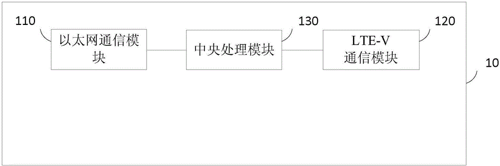
[0056] figure 1 A schematic diagram of the structure of an ETC toll entrance device provided by Embodiment 1 of the present invention. This embodiment is applicable to the situation that vehicles pass through toll stations and pay through ETC. The device can be integrated and configured at the ETC toll entrance, and the ETC toll entrance device 10 includes: an Ethernet communication module 110 , an LTE-V communication module 120 and a central processing module 130 .
[0057] The Ethernet communication module 110 is used to realize the information interaction between the central processing module 130 and the ETC background server through Ethernet;
[0058] The LTE-V communication module 120 is configured to transmit the information based on the LTE-V protocol received from the surrounding environment to the central processing module 130, and send the information received from the central processing module 130 based on the LTE-V protocol. Among them, LTE-V (Long Time Evolution-...
Embodiment 2
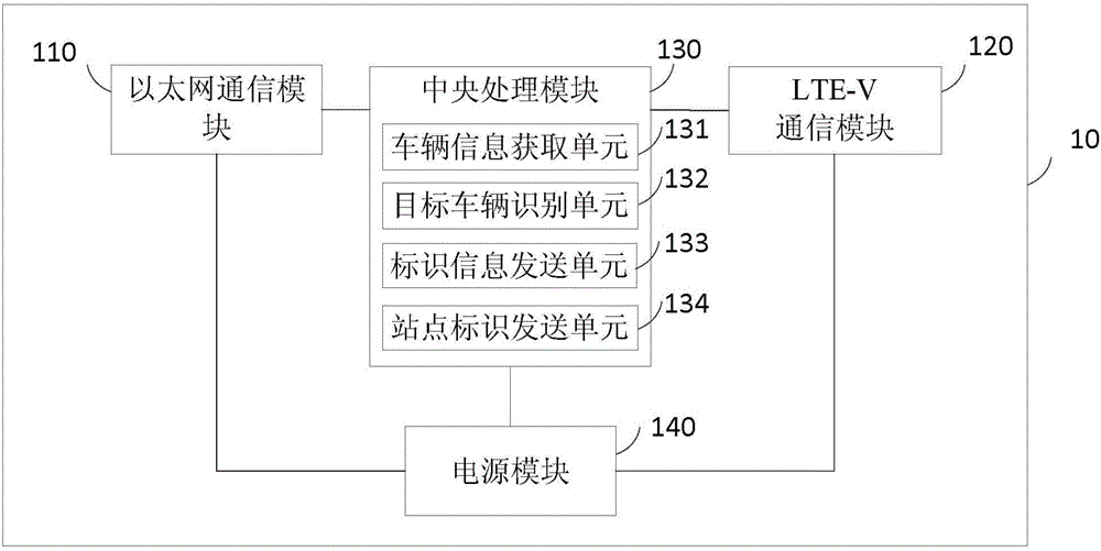
[0063] Figure 2a A schematic structural diagram of an ETC charging entrance device provided in Embodiment 2 of the present invention. The technical solution of this embodiment is further refined on the basis of Embodiment 1, wherein the ETC charging entrance device 10 also includes:
[0064] The power supply module 140 is used to supply power to the Ethernet communication module 110 , the LTE-V communication module 120 and the central processing module 130 .
[0065] Further, the central processing module 130 includes:
[0066] The vehicle information acquisition unit 131 is configured to acquire vehicle information sent by surrounding vehicles based on the LTE-V protocol through the LTE-V communication module 120, wherein the vehicle information includes real-time location information of the vehicle and identification information of the vehicle.
[0067] The target vehicle identification unit 132 is configured to identify the target vehicle in the surrounding vehicles headi...
Embodiment 3
[0091] image 3It is a structural schematic diagram of an ETC toll exit device provided in Embodiment 3 of the present invention. This embodiment is applicable to the situation where vehicles pass through toll stations and pay through ETC. The device can be configured at the ETC toll exit, and the ETC toll exit device 30 It includes: an Ethernet communication module 310 , an LTE-V communication module 320 and a central processing module 330 .
[0092] The Ethernet communication module 310 is used to realize the information exchange between the central processing module 330 and the ETC background server through Ethernet.
[0093] The LTE-V communication module 320 is configured to transmit the information based on the LTE-V protocol received from the surrounding environment to the central processing module 330, and send the information received from the central processing module 330 based on the LTE-V protocol.
[0094] The central processing module 330 is used to carry out in...
PUM
 Abstract
Description
Claims
Application Information