

Power supply switching circuit employing comparator and signal transmission method
A power switching and comparator technology, applied in circuit devices, emergency power arrangements, electrical components, etc., can solve problems such as fixed power switching thresholds, and achieve the effects of accurate thresholds, reduced power consumption, and accurate switching thresholds
- Summary
- Abstract
- Description
- Claims
- Application Information
AI Technical Summary
Problems solved by technology
Method used
Image

Examples
Embodiment 1
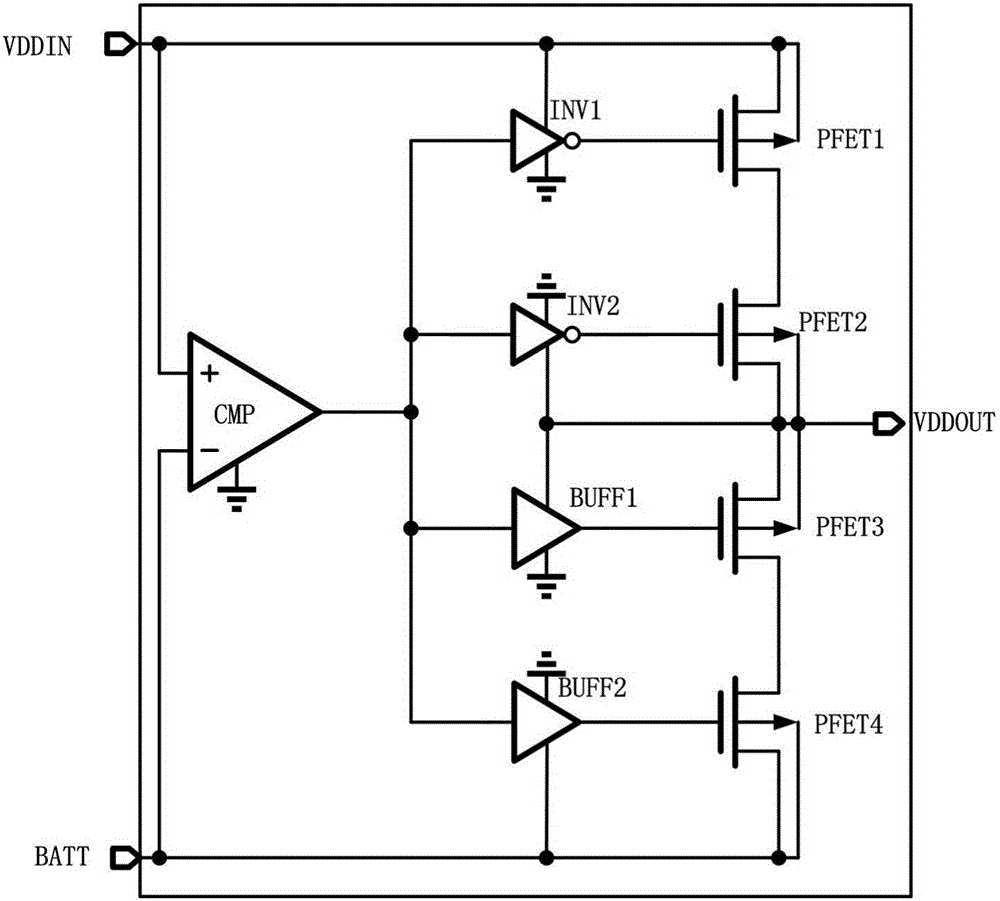
[0049] as attached image 3 As shown, the power switching circuit connection instructions:
[0050] A power switching circuit using a comparator, including a comparator CMP, a first inverter INV1, a second inverter INV2, a first buffer BUFF1, a second buffer BUFF2, a first PMOS switch tube PFET1, a second PMOS switch tube PFET2, third PMOS switch tube PFET3, fourth PMOS switch tube PFET4; the positive terminal of the comparator CMP is connected to the off-chip input power supply VDDIN, the negative terminal is connected to the backup power supply BATT, and the output terminal is connected to the first inverter Input terminals of INV1, the second inverter INV2, the first buffer BUFF1 and the second buffer BUFF2; the power supply of the first inverter INV1 is connected to the off-chip input power supply VDDIN, and the power supply of the second inverter INV2 is connected to the power switch The output VDDOUT of the circuit, the power supply of the first buffer BUFF1 is connecte...
Embodiment 2
[0066] The circuit connection diagram of the power switching circuit is attached image 3 As shown, it has been described in Example 1.
[0067] Such as Figure 5 As shown, the comparator circuit connection instructions:
[0068] The comparator samples the input power supply and the backup power supply voltage to determine whether the off-chip power supply is valid, and the comparator includes a sampling circuit of the off-chip input power supply VDDIN, a bias current generating circuit, a comparator main body, a sampling circuit of the backup power supply BATT and an implementation Mitter trigger.
[0069] The sampling circuit of the off-chip input power supply VDDIN is a MOS transistor series circuit of the off-chip input power supply VDDIN, and the MOS transistor series circuit includes a first voltage-dividing MOS transistor PD1', a second voltage-dividing MOS transistor PD2' and a third NMOS switch tube N3 ', the source of the first voltage-dividing MOS transistor PD1'...
PUM
 Abstract
Description
Claims
Application Information