A primary side current control drive circuit

A primary current and drive circuit technology, which is applied in the field of primary current control drive circuit, can solve the problem that it is difficult to achieve high PF value and low ripple at the same time, so as to avoid the mutual restriction of output ripple and PF value and speed up the loop response The effect of speed, low ripple output

Active Publication Date: 2019-04-02
INVENTRONICS HANGZHOU
View PDF4 Cites 0 Cited by
  • Summary
  • Abstract
  • Description
  • Claims
  • Application Information

AI Technical Summary

Problems solved by technology

[0005] In view of this, the present invention provides a primary current control drive circuit to solve the problem that it is difficult to simultaneously achieve high PF value and low ripple in the prior art, and the primary current control drive circuit provided by the present invention has a high Load Regulation

Method used


Image

  • A primary side current control drive circuit
  • A primary side current control drive circuit
  • A primary side current control drive circuit

Examples


Embodiment Construction

[0043] The following will clearly and completely describe the technical solutions in the embodiments of the present invention with reference to the accompanying drawings in the embodiments of the present invention. Obviously, the described embodiments are only some, not all, embodiments of the present invention. Based on the embodiments of the present invention, all other embodiments obtained by persons of ordinary skill in the art without making creative efforts belong to the protection scope of the present invention.

[0044] The invention provides a primary side current control drive circuit to solve the problem that it is difficult to simultaneously realize high PF value and low ripple in the prior art, and has a high load regulation rate.

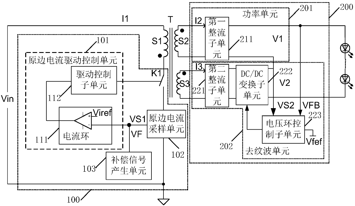
[0045] Specifically, the primary side current control drive circuit, such as figure 2 As shown, including: transformer T, primary side circuit 100 and secondary side circuit 200; wherein:

[0046] The transformer T includes: a primar...


PUM


Abstract

The application provides a primary current control drive circuit, the primary current drive control unit controls the switch tube according to the current reference signal and the first sampling signal output by the primary current sampling unit, so that the primary current is stabilized at a set value, Further, the load current is stabilized, and the set value is adjusted according to the compensation signal output by the compensation signal generating unit, so that the load current does not change with the change of the load voltage, thereby improving the load regulation rate and realizing steady current driving; at the same time, by The anti-ripple unit eliminates or reduces the output ripple after the power unit is connected in series with the anti-ripple unit; it is not necessary to speed up the loop response speed to achieve low ripple output, which avoids the output ripple in the prior art. The wave and PF value are mutually restricted, and it is difficult to take into account the problem at the same time.

Description

technical field [0001] The invention relates to the technical field of LED driving, in particular to a primary side current control driving circuit. Background technique [0002] LED, as a new type of lighting device, is widely used in the field of lighting due to its high luminous efficiency, and it usually requires a steady current drive. In the prior art, the LED driver used as its steady current drive is low in cost and simple in structure. characteristics, a single-stage scheme is often used. [0003] use as figure 1 The single-stage primary-side current driver shown eliminates the complicated optocoupler isolation circuit, but due to the need to take into account the PFC (Power Factor Correction, power factor correction) function, that is, its control loop needs a very slow response speed to have a relatively fast response. The high PF (Power Factor, power factor) value, therefore, the response speed of its control loop is slow, and this will cause the output current...

Claims


Application Information

Patent Timeline
Patent Type & Authority Patents(China)
IPC IPC(8): H02M3/28H02M1/14H05B33/08H05B44/00
CPCH02M1/14H02M3/28H05B45/44H05B45/00
Inventor 梅进光吴孝军姜德来
Owner INVENTRONICS HANGZHOU
Why Eureka
Try Eureka