A voltage-controlled current source circuit

A voltage-controlled current source and current source technology, applied in the direction of adjusting electrical variables, control/regulation systems, instruments, etc., can solve the problems of being susceptible to noise interference, transmission voltage amplitude, and low variation range to achieve a stable load current , reduce loss, increase the effect of output voltage and power

Active Publication Date: 2018-05-25
NORTH CHINA POWER ENG
View PDF5 Cites 1 Cited by
  • Summary
  • Abstract
  • Description
  • Claims
  • Application Information

AI Technical Summary

Problems solved by technology

[0011] Since the output current flows directly through the sense resistor R s , when the output current is large R s The loss and heat on the circuit becomes a problem. If a sampling resistor with a very low resistance value is selected, when the output current is small, the input voltage V i The value is also small, when building a program-controlled current source or connecting with other circuits, the input voltage V i The amplitude and variation range of the transmission voltage are also low, and it is easy to be interfered by noise

Method used


Image

  • A voltage-controlled current source circuit
  • A voltage-controlled current source circuit
  • A voltage-controlled current source circuit

Examples


Embodiment 1

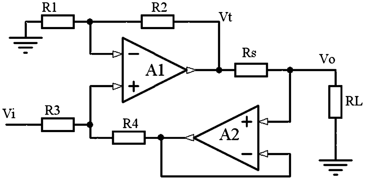
[0043] The invention provides a voltage-controlled current source circuit, the basic circuit of which is as figure 2 shown. Including operational amplifiers A1, A2, resistor R 1 , R 2 , R 3 , R 4 , Sampling resistor R s1 and load resistor R L ; The positive and negative input terminals of the operational amplifier A1 are respectively connected to the resistor R 1 and resistor R 3 One end of the connection, the output of the operational amplifier A1 and the sampling resistor R s1 Connected at one end, the resistor R 1 The other end of the resistor R is grounded and the resistor R 3 The other end is connected to the voltage input terminal, the resistor R 2 The two ends of the operational amplifier A1 are respectively connected to the output terminal and the negative input terminal; the positive input terminal of the operational amplifier A2 is connected to the sampling resistor R s1 The other end is connected, and its negative input and output are respectively connec...

Embodiment 2

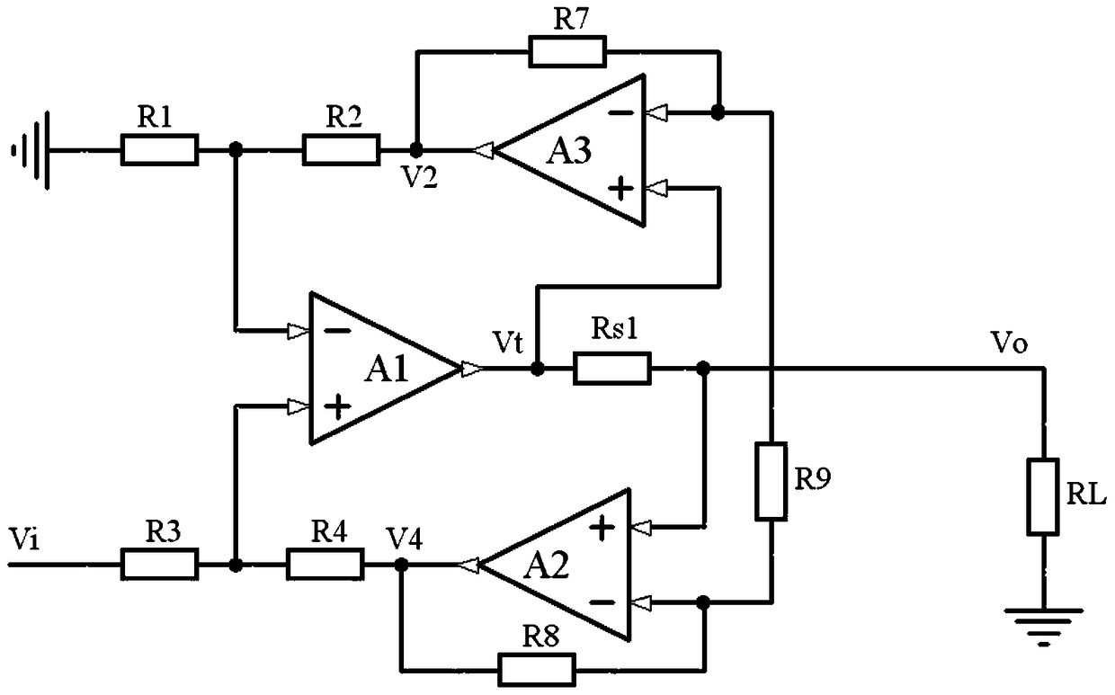
[0058] image 3 given in figure 2 On the basis of , a follower is connected in parallel to double the output current. and figure 2 Compared to this circuit, only an additional operation amplifier A4 and sampling resistor R s2 The follower composed of it can be seen from the circuit that the output voltage of the operational amplifier A4 always follows V t change by image 3 It can be seen that the flow through the sampling resistor R s1 and R s2 The currents are:

[0059] I s1o = (V t -V o ) / R s1

[0060] I s2o = (V t -V o ) / R s2

[0061] flow through the load resistor R L The current is the sum of the above two currents. It can be seen that the output current is increased after adding the follower; if the operational amplifier A4 and the sampling resistor R s2 Respectively with the operational amplifier A1 and the sampling resistor R s1 With exactly the same parameters, the output current is doubled.

[0062] If a follower and a sampling resistor are a...

Embodiment 3

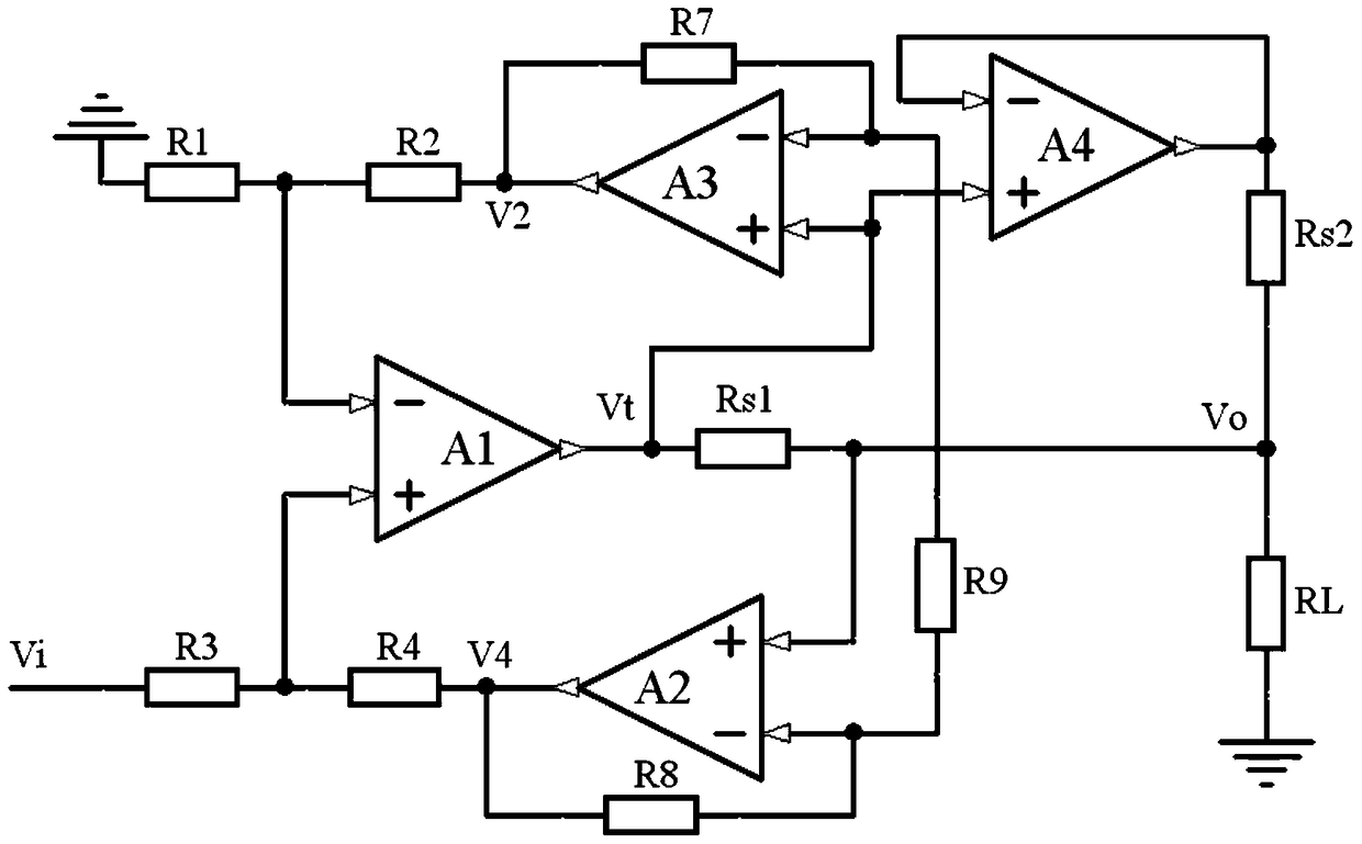
[0065] Figure 4 given in figure 2 A schematic diagram of a scheme to increase the output voltage based on . exist figure 2 The output of the circuit shown is augmented by a resistor R 10 ~R 12 It is an inverting amplifier composed of operational amplifier A5, and the load is connected between the output Vo+ of the voltage-controlled current source and the output Vo- of the newly added inverting amplifier. way to ground the level of the control signal, Figure 4 One way of grounding is given, that is, through two resistors R 5 and R 6 The intermediate level of the control input signal is at the same potential as the ground, and of course other level control methods can also be used.

[0066] against Figure 4 The circuit can also be deduced as follows:

[0067] V i+ -V i- =K 1 K 2 (V t -V o+ )

[0068] The output voltage of operational amplifier A5 V o- for:

[0069] V o- = -R 12 / R 11 V o+

[0070] If take R 11 =R 12 , then add the load resistor R...


PUM


Abstract

The invention discloses a voltage-controlled current source circuit, which relates to the field of electronic circuits and voltage-controlled current sources; the output terminal of the operational amplifier A1 is connected in series with a sampling resistor Rs1 and then output, and the voltage at both ends of the sampling resistor Rs1 passes through the operational amplifiers A2 and A3, the resistor Connectors R7, R8 and R9 are connected as a signal amplifying circuit, the sampling resistor Rs1 output side of the amplifying circuit amplifies the output V4 through the resistor R4 and is connected to the positive input terminal of the operational amplifier A1, and the operational amplifier A1 side of the amplifying circuit Rs1 amplifies the output V2 through The resistor R2 is connected to the negative input terminal of the operational amplifier A1, and the positive and negative input terminals of the operational amplifier A1 are also respectively connected to the voltage dividing resistors R3 and R1. It is implemented by an operational amplifier circuit. Based on the current source circuit implemented by a typical operational amplifier, the voltage drop on the current sampling resistor in the output loop is amplified and fed back to the input terminal of the operational amplifier by increasing the amplification, reducing the voltage of the sampling resistor. drop and power consumption, increasing the input voltage range of the voltage-controlled current source.

Description

technical field [0001] The invention relates to the field of electronic circuit and current source, more specifically, relates to a voltage-controlled current source circuit, which mainly completes the conversion from voltage to current and realizes the function of the voltage-controlled current source. Background technique [0002] Voltage-controlled current source or program-controlled current source is an indispensable instrument for electrical measurement, measurement calibration, and electrical test, and is widely used in industrial and mining enterprises and laboratories. [0003] In current source circuits that require relatively high power, power devices such as field effect transistors and Darlington transistors are commonly used to convert voltage to current, and open-loop control methods are often used, so their accuracy is low. In the low-power applications of electronic circuits, operational amplifiers and voltage stabilizing circuit devices are often used to im...

Claims


Application Information

Patent Timeline
Patent Type & Authority Patents(China)
IPC IPC(8): G05F1/575
Inventor 王绍德徐珂朱芸杨正莉康海燕任树东
Owner NORTH CHINA POWER ENG
Why Eureka
Try Eureka