Voltage-controlled current source circuit
A technology of voltage-controlled current source and current source, which is applied in the direction of adjusting electrical variables, control/regulation systems, instruments, etc., can solve the problems of transmission voltage amplitude, low variation range, and susceptibility to noise interference, etc., to reduce loss, The effect of smoothing load current and reducing voltage requirements
- Summary
- Abstract
- Description
- Claims
- Application Information
AI Technical Summary
Problems solved by technology
Method used
Image
Examples
Embodiment 1
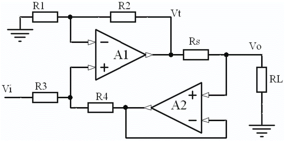
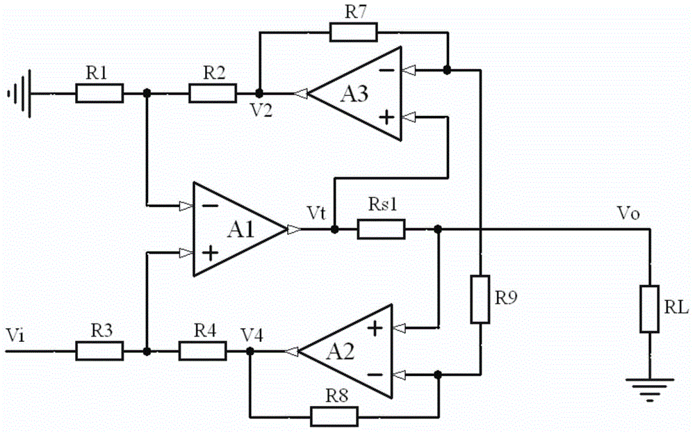
[0043] The invention provides a voltage-controlled current source circuit, the basic circuit of which is as figure 2 shown. Including operational amplifiers A1, A2, resistor R 1 , R 2 , R 3 , R 4 , Sampling resistor R s1 and load resistor R L ; The positive and negative input terminals of the operational amplifier A1 are respectively connected to the resistor R 1 and resistor R 3 One end of the connection, the output of the operational amplifier A1 and the sampling resistor R s1 Connected at one end, the resistor R 1 The other end of the resistor R is grounded and the resistor R 3 The other end is connected to the voltage input terminal, the resistor R 2 The two ends of the operational amplifier A1 are respectively connected to the output terminal and the negative input terminal; the positive input terminal of the operational amplifier A2 is connected to the sampling resistor R s1 The other end is connected, and its negative input and output are respectively connec...
Embodiment 2
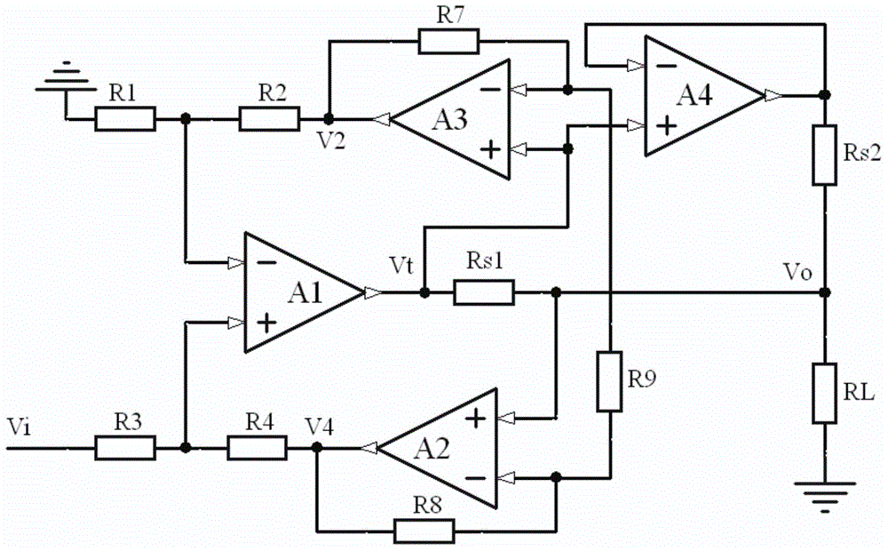
[0058] image 3 given in figure 2 On the basis of , a follower is connected in parallel to double the output current. and figure 2 Compared to this circuit, only an additional operation amplifier A4 and sampling resistor R s2 The follower composed of it can be seen from the circuit that the output voltage of the operational amplifier A4 always follows V t change by image 3 It can be seen that the flow through the sampling resistor R s1 and R s2 The currents are:
[0059] I s1o =(V t -V o ) / R s1
[0060] I s2o =(V t -V o ) / R s2
[0061] flow through the load resistor R L The current is the sum of the above two currents. It can be seen that the output current is increased after adding the follower; if the operational amplifier A4 and the sampling resistor R s2 Respectively with the operational amplifier A1 and the sampling resistor R s1 With exactly the same parameters, the output current is doubled.
[0062] If a follower and a sampling resistor are added...
Embodiment 3
[0065] Figure 4 given in figure 2 A schematic diagram of a scheme to increase the output voltage based on . exist figure 2 The output of the circuit shown is augmented by a resistor R 10 ~R 12 It is an inverting amplifier composed of operational amplifier A5, and the load is connected between the output Vo+ of the voltage-controlled current source and the output Vo- of the newly added inverting amplifier. In order to avoid the upper and lower limits of the output, the input voltage cannot be directly grounded, and multiple way to ground the level of the control signal, Figure 4 One way of grounding is given, that is, through two resistors R 5 and R 6 The intermediate level of the control input signal is at the same potential as the ground, and of course other level control methods can also be used.
[0066] against Figure 4 The circuit can also be deduced as follows:
[0067] V i+ -V i- = K 1 K 2 (V t -V o+ )
[0068] The output voltage of operational ampl...
PUM
 Abstract
Description
Claims
Application Information
 - R&D
- Intellectual Property
- Life Sciences
- Materials
- Tech Scout
- Unparalleled Data Quality
- Higher Quality Content
- 60% Fewer Hallucinations
Browse by: Latest US Patents, China's latest patents, Technical Efficacy Thesaurus, Application Domain, Technology Topic, Popular Technical Reports.
© 2025 PatSnap. All rights reserved.Legal|Privacy policy|Modern Slavery Act Transparency Statement|Sitemap|About US| Contact US: help@patsnap.com


