Neutral point clamped power conversion device and its control method

A power conversion device, neutral point clamping technology, applied in the output power conversion device, electrical components, AC power input into DC power output and other directions, can solve the problems of DC voltage and DC voltage imbalance, different symbols and other problems

Active Publication Date: 2019-09-17
KK TOSHIBA
View PDF8 Cites 0 Cited by
  • Summary
  • Abstract
  • Description
  • Claims
  • Application Information

AI Technical Summary

Problems solved by technology

[0004] However, since the harmonic current is relatively large compared to the fundamental current when the load current is small, for example, a value close to zero, there is a sign and detection of the fundamental current that contributes to the fluctuation of the neutral point potential. The case where the sign of the load current differs
As a result, the sign of the calculated zero-phase voltage is sometimes opposite to the sign that should be applied, and there is a problem that the DC voltage on the high-potential side and the DC voltage on the low-potential side are unbalanced.

Method used


Image

  • Neutral point clamped power conversion device and its control method
  • Neutral point clamped power conversion device and its control method
  • Neutral point clamped power conversion device and its control method

Examples


no. 1 Embodiment approach

[0024] First, the first embodiment will be described.

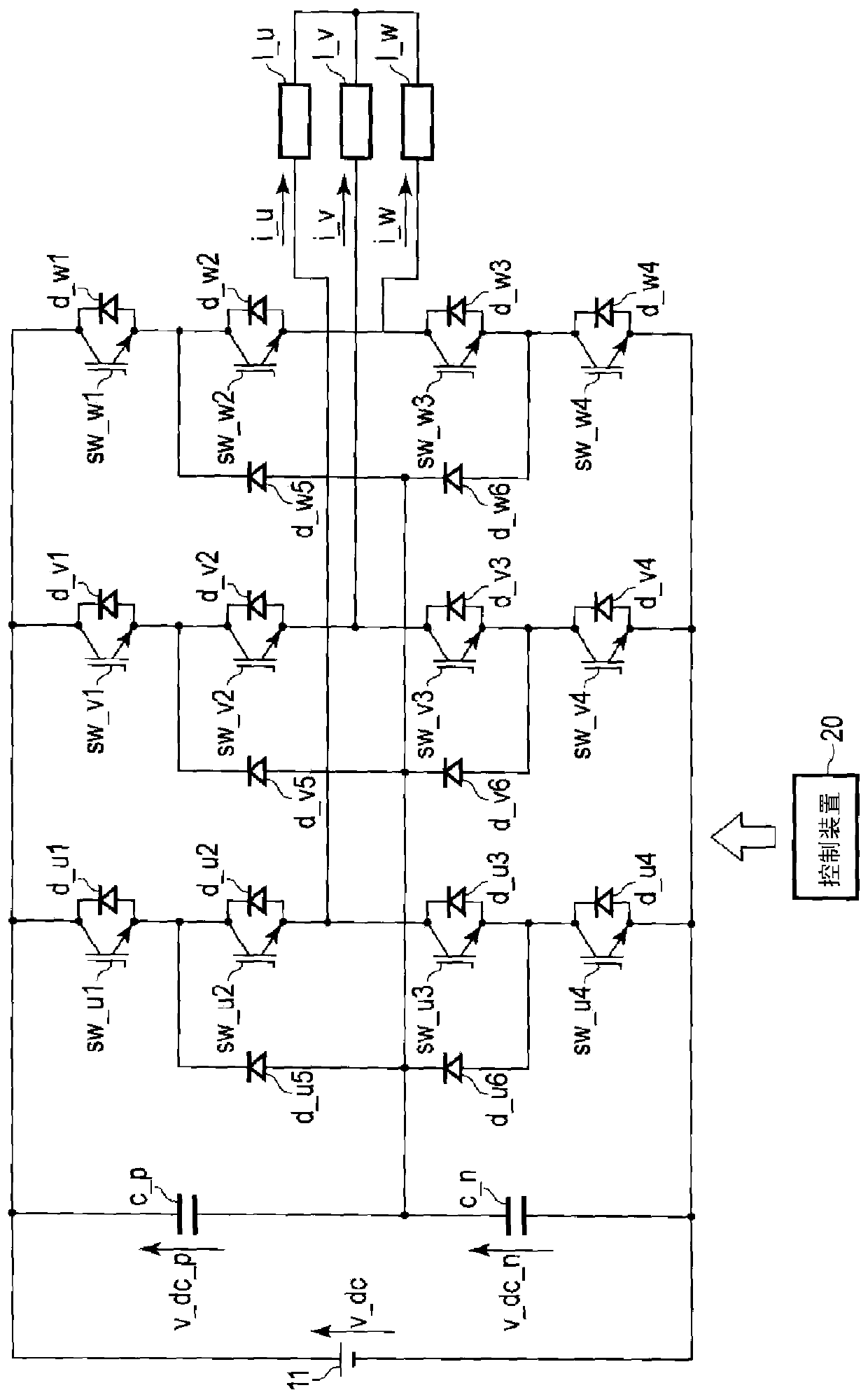
[0025] figure 1 It is a figure which shows the structural example of the neutral point clamp type power conversion apparatus in 1st Embodiment.

[0026] In the first embodiment, if figure 1 As shown, as an inverter (inverter), in a neutral-point clamped power conversion device that drives three-phase loads of U-phase, V-phase, and W-phase, three NPCs (Neytral- Point-Clamped) pins (legs) are connected in parallel. Between the high potential side terminal and the low potential side terminal of the DC power supply 11 , a high potential side capacitor c_p and a low potential side capacitor c_n are connected in series, and the connection point of these capacitors forms a neutral point. That is, the DC input voltage v_dc of the DC power supply 11 is divided into a DC voltage v_dc_p and a DC voltage v_dc_n by the capacitor c_p on the high potential side and the capacitor c_n on the low potential side, and a neutral point pote...

no. 2 Embodiment approach

[0060] Next, a second embodiment will be described. Among the configurations of the following embodiments, detailed descriptions of the same parts as those described in the first embodiment will be omitted.

[0061] Figure 4 It is a figure which shows the structural example of the neutral point clamp type power conversion apparatus in 2nd Embodiment. Figure 5 It is a figure which shows the example of the structure of the NPC pin of the neutral point clamp type power conversion apparatus in 2nd Embodiment.

[0062] In the second embodiment, such as Figure 4 In the neutral point clamp type power conversion device that drives three-phase loads l_u, l_v, and l_w of U phase, V phase, and W phase as a converter as shown, there are two loads connected in parallel for each phase. The configuration of 6 NPC pins in total is the configuration of using 3 single-phase NPC pins to supply current to a 3-phase load.

[0063] Similar to the first embodiment, between the high potential ...


PUM


Abstract

The present invention relates to a control device and a control method of a neutral point clamp type power conversion device. This control device has: a 3-phase 2-phase conversion unit, which converts the 3-phase current flowing in the 3-phase load driven by the neutral point clamp type power conversion device into the d-axis current and the q-axis current of the rotating coordinate system. The point-clamp type power conversion device is connected to a DC power supply with 3 potentials to perform 3-level voltage output; the 2-phase 3-phase current conversion unit will make the d-axis current and q-axis current pass through the three-phase current. The d-axis filter current and q-axis filter current after the filter with a large time constant of the reciprocal of the fundamental frequency are converted into 3-phase current; the calculation unit calculates as The zero-phase voltage command value that controls the voltage obtained by dividing the DC input voltage at the neutral point of the power conversion device is a command value superimposed on the three-phase voltage command values ​​for the power conversion device.

Description

technical field [0001] Embodiments of the present invention relate to a neutral point clamped power conversion device and a control method thereof. Background technique [0002] A neutral-point clamped (NPC (Neutral-Point-Clamped)) power conversion device is configured by connecting at least four switching elements in series, and can output a high voltage of several kV to several tens of kV. In addition, since the neutral point clamp type power conversion device outputs phase voltages of three levels, harmonics are small. Therefore, it is possible to supply a current with a small ripple in the waveform and a smooth waveform to the load. In addition, since two of the above-mentioned four switching elements are switched at the same timing, and the remaining two are not switched, the switching loss of the entire device can be reduced. Therefore, neutral point clamped power conversion devices are often used in railway vehicles, industrial drive devices, power system voltage st...

Claims


Application Information

Patent Timeline
Patent Type & Authority Patents(China)
IPC IPC(8): H02M7/487
CPCH02M7/487H02M1/0064
Inventor 长谷川隆太石月照之藤田崇
Owner KK TOSHIBA
Why Eureka
Try Eureka