Three-phase brushless direct current motor adaptive commutation angle compensation method

A technology of brushed DC motor and commutation angle, which is applied in the direction of electronic commutator, torque ripple control, etc., can solve the problem of high calculation cost, and achieve the effect of low economic cost, convenient use, and stable operation of the motor

Inactive Publication Date: 2016-09-21
曹子沛
View PDF3 Cites 19 Cited by
  • Summary
  • Abstract
  • Description
  • Claims
  • Application Information

AI Technical Summary

Problems solved by technology

[0007] The purpose of the present invention is to provide an adaptive commutation angle compensation method for a three-phase brus

Method used


Image

  • Three-phase brushless direct current motor adaptive commutation angle compensation method
  • Three-phase brushless direct current motor adaptive commutation angle compensation method
  • Three-phase brushless direct current motor adaptive commutation angle compensation method

Examples


Embodiment Construction

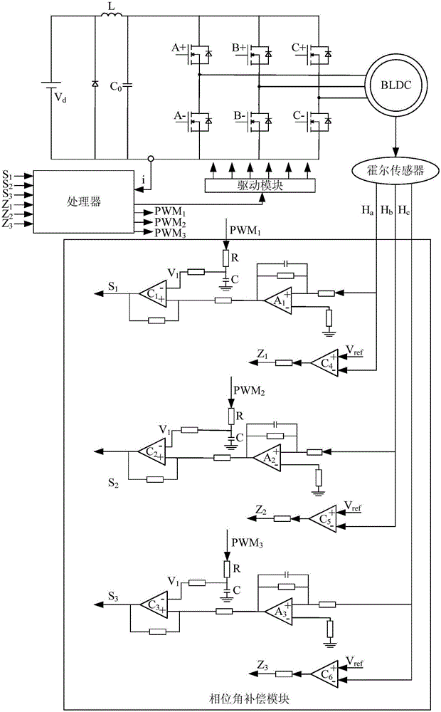
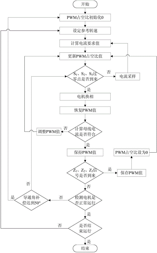
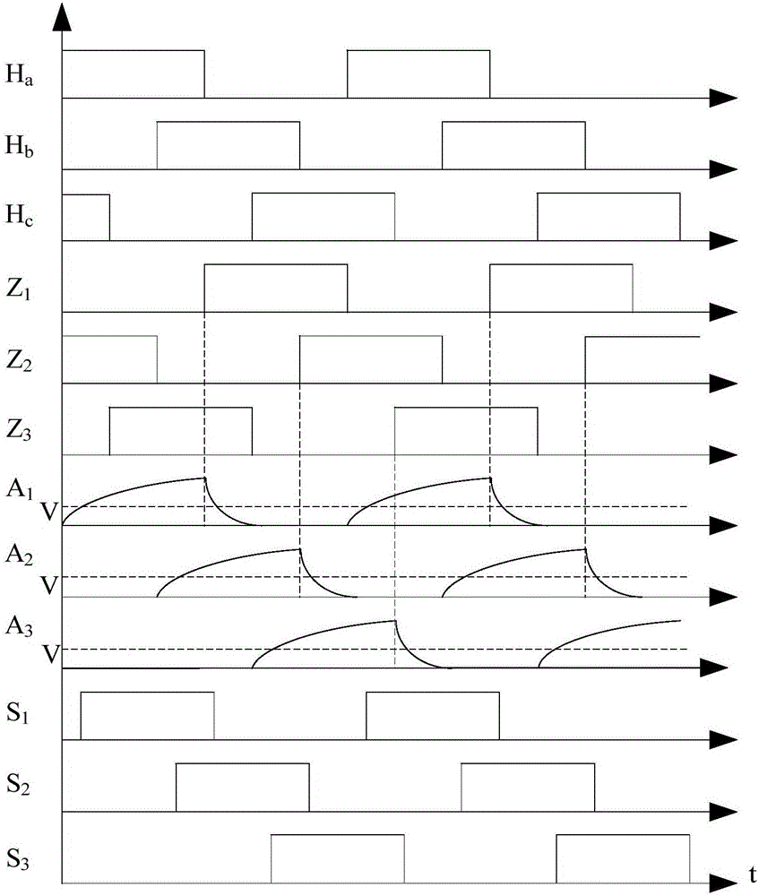
[0017] An adaptive commutation angle compensation method for brushless DC motors, the principle block diagram of adaptive commutation angle compensation is shown in figure 1 As shown, this method is completed through the combination of software and hardware. The commutation angle compensation circuit is composed of three delay circuits. Each delay circuit completes the delay function through the combination of an integrating circuit and a comparator. The delay time is input by the processor. The PWM duty cycle of the phase angle compensation circuit is determined by the size, the delay time increases when the PWM duty cycle is large, and the delay time decreases when the PWM duty cycle is small. The Hall signal is delayed by the commutation angle compensation circuit and enters the processor. The delay time does not exceed 50° electrical angle, and the processor performs commutation according to this signal. In each conduction stage, the processor detects the bus current, calc...


PUM


Abstract

The present invention discloses a three-phase brushless direct current motor adaptive commutation angle compensation method. A hardware commutation angle compensation module is added, and the size of the commutation angle compensation is controlled through the PWM signals of the processor. The size of the current of the bus of each phase conduction phase is detected, the current mean value of the bus is calculated, and the current mean value is compared with the reference value to control the increasing and decreasing of the PWM signal duty cycle and reach the purpose of adaptively regulating the commutation angle compensation.

Description

technical field [0001] The invention relates to the field of motor control methods, in particular to an adaptive commutation angle compensation method for a three-phase brushless DC motor. Background technique [0002] Brushless DC motors are usually equipped with Hall sensors to observe the rotor position information. Three-phase brushless DC motors are equipped with three Hall sensors. When the Hall sensor jumps from low level to high level, it means that the reverse The electromotive force zero crossing point needs to be delayed by a certain electrical angle under normal circumstances, so as to ensure positive and negative synchronization with the phase current, so that the electromagnetic torque can ensure that no negative value occurs. An angle is the so-called commutation angle. The commutation angle changes with the speed, the faster the speed, the larger the commutation angle, and the slower the speed, the smaller the commutation angle. Proper compensation of the c...

Claims


Application Information

Patent Timeline
IPC IPC(8): H02P6/16H02P6/10
CPCH02P6/10H02P6/16
Inventor 曹子沛葛木明曹学林朱洪萍
Owner 曹子沛
Why Eureka
Try Eureka