
PWM control circuit and PWM signal generation method

A PWM signal and control circuit technology, applied in the direction of pulse generation, electrical components, generation of electrical pulses, etc., can solve the problems of complex system control and large chip area, and achieve the effect of increasing flexibility and broadening the scope.

Active Publication Date: 2016-09-21
SILERGY SEMICON TECH (HANGZHOU) CO LTD
View PDF4 Cites 3 Cited by
  • Summary
  • Abstract
  • Description
  • Claims
  • Application Information

AI Technical Summary

Problems solved by technology

[0006] In view of this, the present invention provides a PWM control circuit and a PWM signal generation method to solve the problem of complex system control and large chip area in the prior art

Method used


Image

  • PWM control circuit and PWM signal generation method
  • PWM control circuit and PWM signal generation method
  • PWM control circuit and PWM signal generation method

Examples


Embodiment Construction

[0041] The present invention is described below based on examples, but the present invention is not limited to these examples. In the following detailed description of the invention, some specific details are set forth in detail. The present invention can be fully understood by those skilled in the art without the description of these detailed parts. In order not to obscure the essence of the present invention, well-known methods, procedures, procedures, components and circuits have not been described in detail.

[0042] Additionally, those of ordinary skill in the art will appreciate that the drawings provided herein are for illustrative purposes and are not necessarily drawn to scale.

[0043] Meanwhile, it should be understood that in the following description, "circuit" refers to a conductive loop formed by at least one element or sub-circuit through electrical connection or electromagnetic connection. When an element or circuit is said to be "connected to" another eleme...


PUM


Abstract

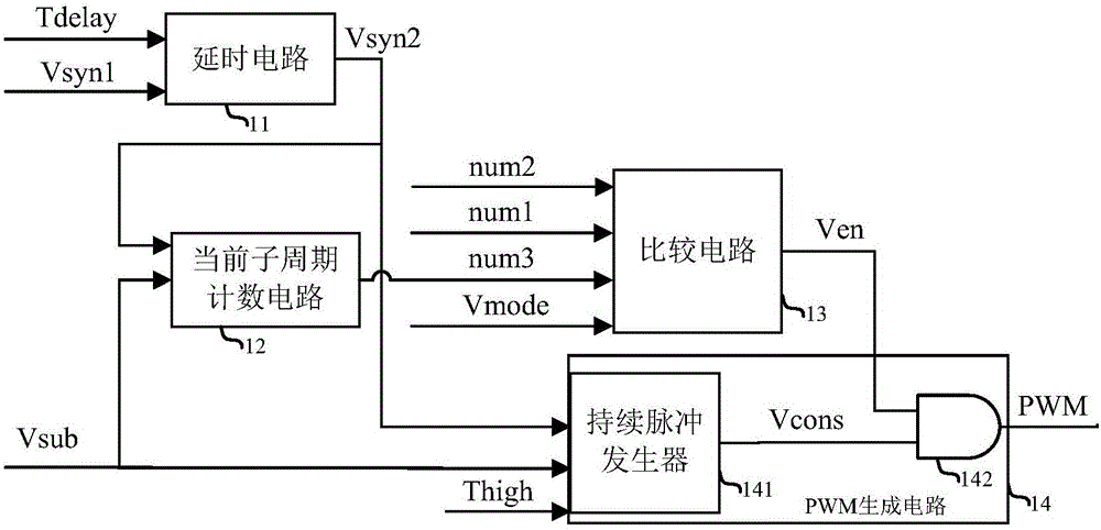
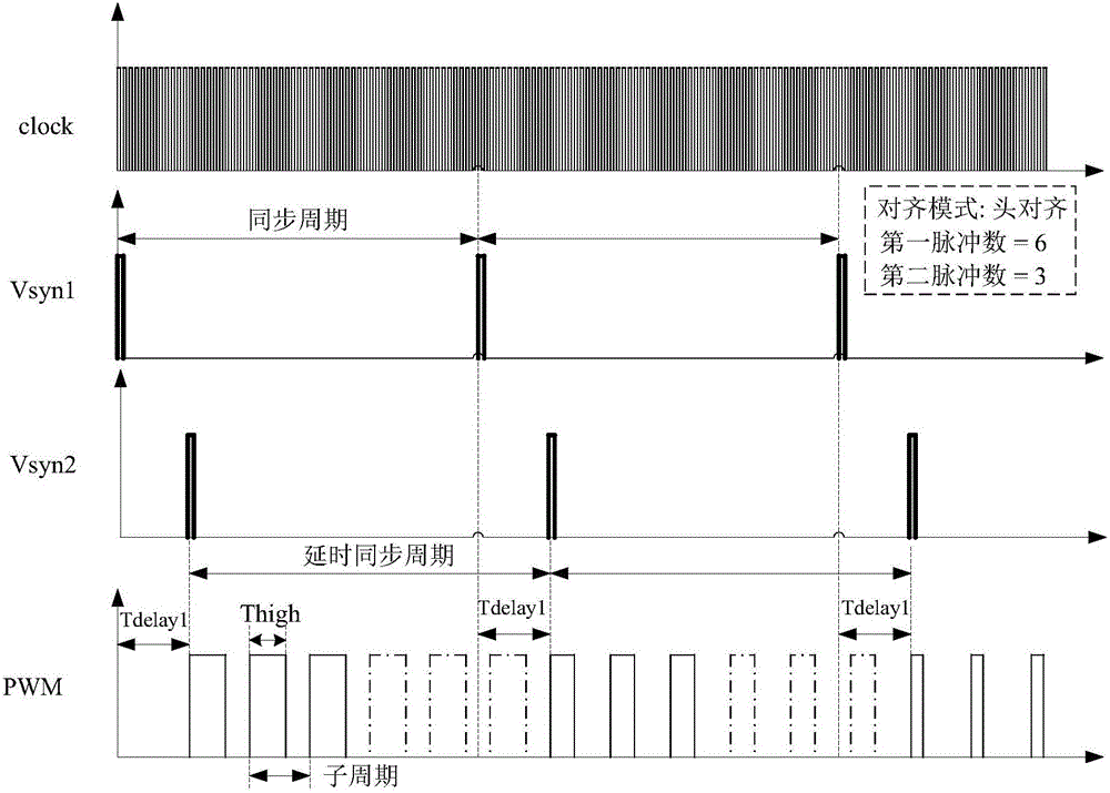
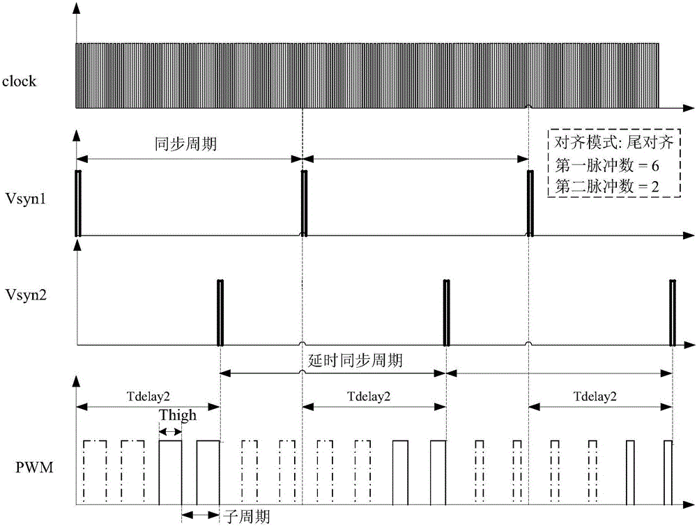
The present invention discloses a PWM control circuit and a PWM signal generation method. Through setting the number of sub-cycles, the number of actually outputted pulses and the high-level time of each pulse in a synchronization cycle, the average duty cycle of a PWM signal is adjusted, thus the driving requirement is satisfied, the flexibility of system regulation is greatly improved, and on the basis of not increasing the system control complexity, the average of the average duty cycle of the PWM signal is broaden. The PWM control circuit of the technology of the invention can output multiple paths of PWM signals, and the parameter of each path can be independently set according to the needs of the users. In each path of PWM signal, the alignment mode of the pulse can be freely set according to the needs of the users, and thus the PWM control circuit of the technology of the invention can satisfy the various requirements of the users.

Description

technical field [0001] The invention relates to a power electronic technology, more specifically, to a PWM control circuit and a PWM signal generating method applied in a backlight circuit. Background technique [0002] In the electronics industry, backlighting is a form of lighting that is often used on LCD displays. The difference between the backlight type and the front light type is that the backlight is illuminated from the side or the back, and the backlight type is used to increase the illuminance in low light source environments and the brightness on computer monitors and LCD screens. In LCD TV systems, light-emitting diodes (LEDs) are used as backlights to illuminate the pixels. [0003] In the prior art, a method for realizing LED dimming is to directly adjust the output current to a desired range, and the output current is used to drive the LED to emit light. Typically, the output current is varied from a non-zero minimum value to a maximum output current. [0...

Claims


Application Information

Patent Timeline
Patent Type & Authority Applications(China)
IPC IPC(8): H03K3/017H03K7/08H03K5/01
CPCH03K3/017H03K5/01H03K7/08
Inventor 王雪晴
Owner SILERGY SEMICON TECH (HANGZHOU) CO LTD
Learn More