Milk-frothing device with dynamic mixing unit, and beverage maker containing the same

A dynamic mixing and foaming device technology, applied in mixers, beverage preparation devices, kitchen utensils, etc., can solve the problems of mutual influence, limited variability, small flexibility, etc., and achieve the effect of improving foamability

Active Publication Date: 2016-09-21
WMF GRP
View PDF6 Cites 5 Cited by
  • Summary
  • Abstract
  • Description
  • Claims
  • Application Information

AI Technical Summary

Problems solved by technology

A big disadvantage of the known system is especially the small flexibility due to the generally high operating pressure (required to pass through very small diaphragms in the line)
This results in components such as pumps, continuous heaters, etc. being only usable and interacting within a very narrow range
This results in a correspondingly limited variability

Method used


Image

  • Milk-frothing device with dynamic mixing unit, and beverage maker containing the same
  • Milk-frothing device with dynamic mixing unit, and beverage maker containing the same
  • Milk-frothing device with dynamic mixing unit, and beverage maker containing the same

Examples


Embodiment Construction

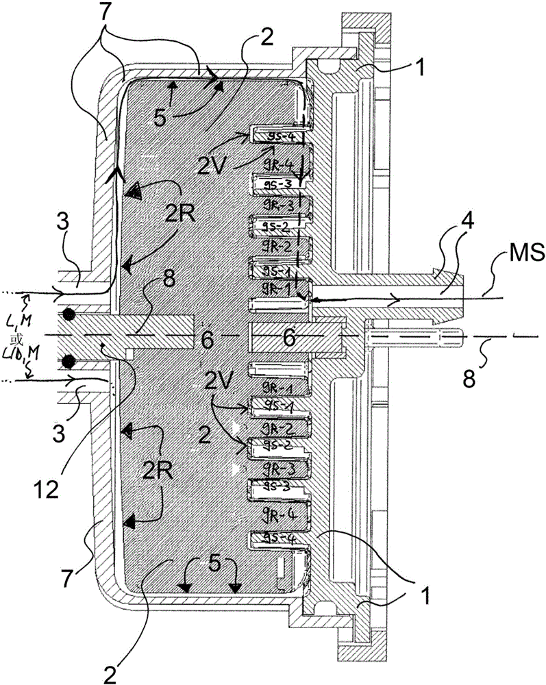
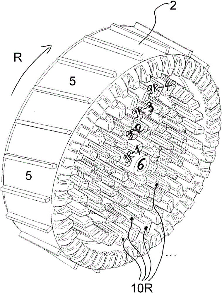
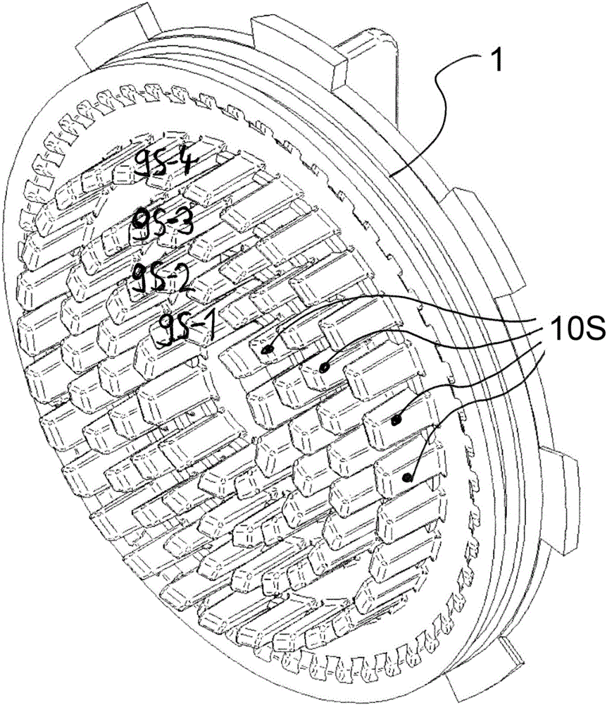
[0057] figure 1 A first milk frothing device according to the invention is shown in cross section in the plane through which the axis of rotation 8 of the stator-rotor assembly extends. Figure 2a shows a three-dimensional view, and image 3 a shows a top view (parallel to the axis of rotation 8 ) of the rotor 2 of the milk frothing device. Figure 2b shows a three-dimensional view, and image 3 b shows a top view (parallel to the axis of rotation 8 ) of the stator 1 of the milk frothing device.

[0058] Such as figure 1 As shown, the conveying channel 3 , which here comprises two partial channels, leads parallel to the axis of rotation 8 , but at a distance therefrom, as far as directly onto the rear surface 2R of the rotor 2 . This conveying channel 3 serves to convey milk M and air L or a milk M and air-steam mixture to the rear surface 2R of the rotor 2 . The rear side 2R (as far as the gap) is positively surrounded by the housing part 7 of the milk frothing device. ...


PUM

PropertyMeasurementUnit
diameteraaaaaaaaaa

Abstract

The invention relates to a milk-frothing device with a dynamic mixing unit, having a stator (1) and a rotor (2), which can be made to rotate (R) relative to the stator (1), wherein the rotor (2) and stator (1) are designed such that milk (M) and air (L, L/D) first of all can be directed to (3) the dynamic mixing unit, then can be subjected a number of times to a shearing action for frothing purposes in the dynamic mixing unit, by rotation (R) of the rotor (2) relative to the stator (1), and finally can be directed out (4) of the dynamic mixing unit.

Description

technical field [0001] The present invention relates to a milk frothing device with a dynamic mixing unit and to a beverage preparation device (in particular: an electrically operated coffee machine, such as a fully automatic coffee machine) comprising such a milk frothing device. Furthermore, the invention relates to a corresponding milk frothing method. Background technique [0002] Modern coffee machines that serve milk or milk froth or mixed drinks also serve cold milk or cold milk froth. To alternatively provide cold or hot milk or milk froth, expensive systems are used: for example there are devices for avoiding heaters (for example see EP2120656B1) or for generating and for outputting cold or hot Completely separate (dual) paths of products (see eg EP2294952B1). [0003] The disadvantage here is the high system-side costs. This therefore also leads to the fact that, due to the significantly different viscosity, a significantly higher energy value is required for fr...

Claims


Application Information

Patent Timeline
Patent Type & Authority Applications(China)
IPC IPC(8): A47J43/12A47J31/44
CPCA47J43/121A47J31/4485B01F23/2351B01F23/2363B01F35/2115B01F35/2217B01F35/3204B01F35/22162B01F35/221422B01F23/237611B01F2101/07
Inventor 桑德尔·多尔内尔托比亚斯·屈希勒尔约亨·格斯曼
Owner WMF GRP
Why Eureka
Try Eureka