Method for manufacturing part by means of additive manufacturing technique

A manufacturing technology, a technology for components, applied in the field of additive manufacturing, which can solve the problems of high cost and time-consuming correction of manufacturing steps or additional support structures

Inactive Publication Date: 2016-09-28
ANSALDO ENERGIA IP UK LTD
View PDF13 Cites 1 Cited by
  • Summary
  • Abstract
  • Description
  • Claims
  • Application Information

AI Technical Summary

Problems solved by technology

Furthermore, corrective manufacturing steps or additional support structures are costly and time-consuming

Method used


Image

  • Method for manufacturing part by means of additive manufacturing technique
  • Method for manufacturing part by means of additive manufacturing technique
  • Method for manufacturing part by means of additive manufacturing technique

Examples


Embodiment Construction

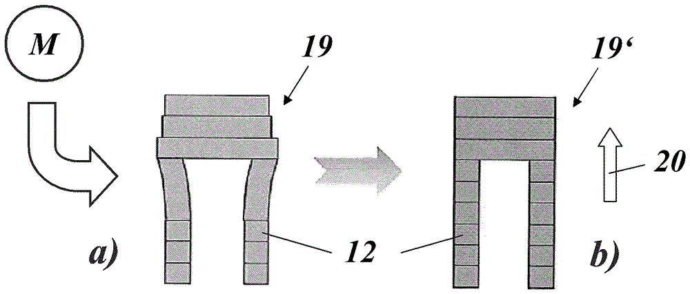
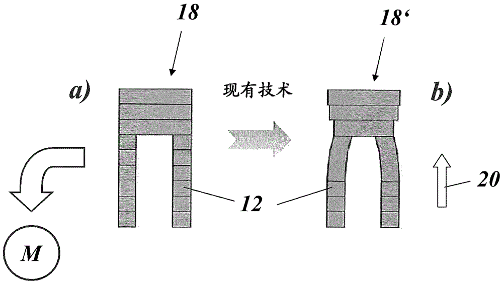
[0045] The method used by the present invention is fundamentally different from the method according to the above-mentioned document EP 2361720B1: in the present invention, the (original) CAD profile (18 in Fig. Gradient CAD designs of different shapes of the resulting part 19' (19 in Fig. 3(a)).

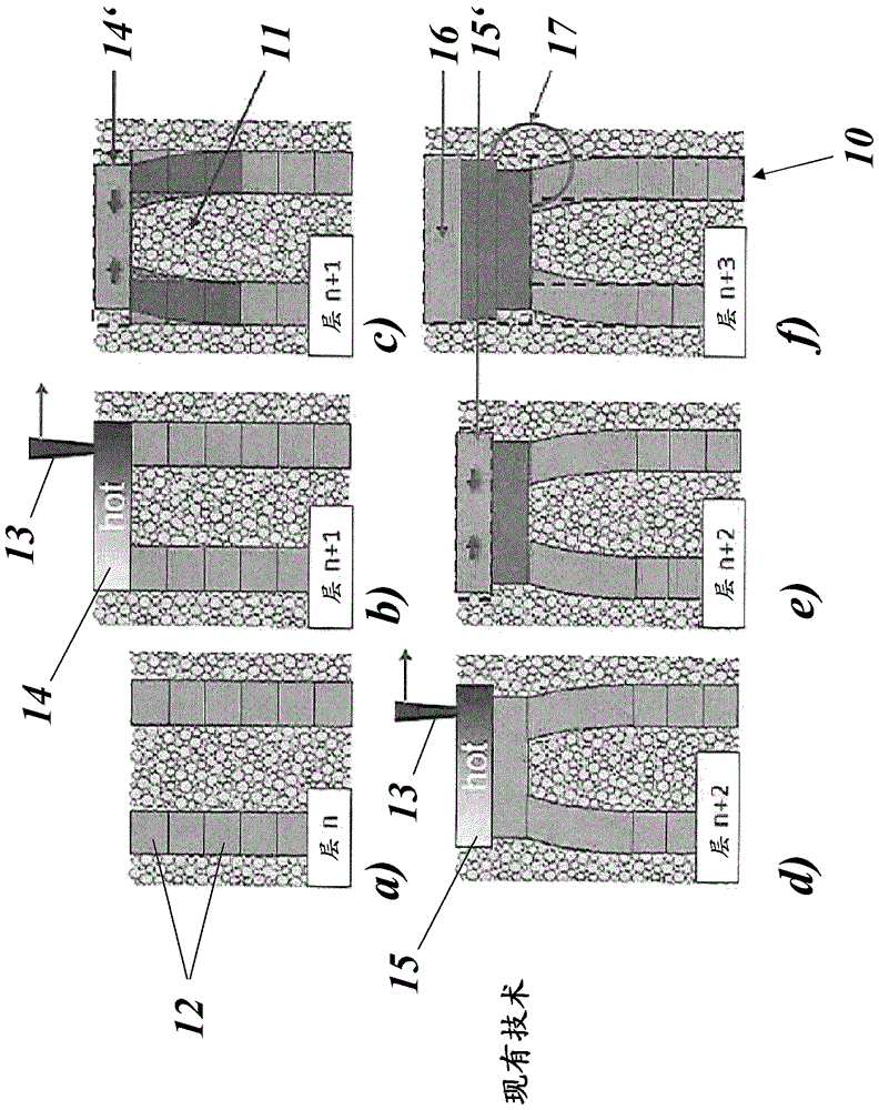
[0046] This is done by taking into account all deformations / distortions that will occur during the SLM process and all related subsequent post-AM fabrication steps (eg removal of the component from the substrate plate, heat treatment HT, etc.). Thus, although the SLM process uses as input a CAD section 19 (which has a different geometry than the target component 19'), the final result (19' in Figure 3(b)) will be completely accurate to the target design (CAD design 18) match, whereas fabrication based on the non-gradient CAD design 18 results in a distorted component 18' (Fig. 2(b)).

[0047] Essentially, the geometry of a part to be manufactured using additive manufacturing techni...


PUM


Abstract

The title of the invention is method for manufacturing part by means of additive manufacturing technique. The invention relates to a method for manufacturing a part (19') by means of an additive manufacturing technique and by post additive manufacturing process steps. A cheaper and faster serial production of such parts is achieved by said method comprising the steps of: providing first CAD data (18) representing the final geometry of the part to be manufactured; converting said first CAD data (18) into second morphed CAD data (19) by means of a morphing process (M), whereby said morphing process (M) takes into consideration all distortions of part geometry, which develop during the additive manufacturing process and the post additive manufacturing process steps such that the part (19') manufactured in accordance with said second morphed CAD data (19) has a geometry in accordance with said first CAD data (18); and manufacturing said part (19') by means of said additive manufacturing technique in accordance with said second morphed CAD data (19).

Description

technical field [0001] The present invention relates to the technology of additive manufacturing. It relates to a method for manufacturing components by additive manufacturing techniques. Background technique [0002] Additive Manufacturing (AM) provides components (or assemblies) that are distorted in their geometry. Causes of distortion are eg relaxation of residual stresses during heat treatment (HT) (after the additive manufacturing process) or deformations (shrinkage, warping, etc.) that have occurred during the additive manufacturing process itself. As AM processes, all methods of metallurgically joining powders (eg sintering, welding, melting) using high energy beams (eg electrons or lasers) are considered. During the course of this document, the example AM ​​process "Selective Laser Melting (SLM)" is used to illustrate specific phenomena. However, this is not to limit generality. [0003] In many cases, this in-situ distortion is attributed to the "standard" desi...

Claims


Application Information

Patent Timeline
Patent Type & Authority Applications(China)
IPC IPC(8): B22F3/105B33Y50/02B33Y10/00
CPCB22F10/00B22F10/66B22F10/28B22F10/80B22F10/64B33Y50/00G06F30/00Y02P10/25B23K15/02B23K15/0086B23K26/342B23K26/70B33Y10/00B33Y50/02
Inventor G.莫内塔H.布兰德T.科特克M.霍伊贝J.舒尔布F.罗伊里格
Owner ANSALDO ENERGIA IP UK LTD
Why Eureka
Try Eureka