Valve element column feeding mechanism of electronic drain valve element assembling machine

An electronic drain valve and spool column technology, applied in metal processing, metal processing equipment, manufacturing tools, etc., can solve problems such as prone to defective products, long assembly cycle, and low efficiency, and achieve the goal of reducing production costs and saving labor Effect

Active Publication Date: 2016-09-28
JIANGSU JIARUN RAINMAKER
View PDF5 Cites 10 Cited by
  • Summary
  • Abstract
  • Description
  • Claims
  • Application Information

AI Technical Summary

Problems solved by technology

[0002] The electronic drain valve is an industrial valve actuator, which is widely used in filters, separators, dryers, drip feet of air tanks and other compressed air system components to automatically discharge condensed water. The existing electronic drain valves are mainly assembled manually. , there are human factors in manual assembly, it is prone to defective products, and the assembly cycle is long, the efficiency is low and the cost is high. In view of this, based on the defects and deficiencies of the existing technology, a spool of an electronic drain valve spool assembly machine is designed Column feeding mechanism

Method used


Image

  • Valve element column feeding mechanism of electronic drain valve element assembling machine
  • Valve element column feeding mechanism of electronic drain valve element assembling machine
  • Valve element column feeding mechanism of electronic drain valve element assembling machine

Examples


Embodiment Construction

[0019] The preferred embodiments of the present invention will be described in detail below in conjunction with the accompanying drawings, so that the advantages and features of the invention can be more easily understood by those skilled in the art, so as to define the protection scope of the present invention more clearly.

[0020] see Figure 1 to Figure 8 , the embodiment of the present invention includes:

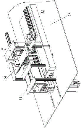
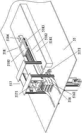
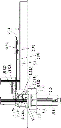
[0021] A spool column feeding mechanism of an electronic drain valve spool assembly machine, the spool column feeding mechanism of the electronic drain valve spool assembly machine includes a spool column feeding device 51 installed on a workbench 55, a spool column Column feeding manipulator 52, spool column transposition device 53 and material box unloading device 54, described spool column feeding manipulator 52 transports the workpiece at the spool column feeding device 51 to the spool column on its right side At the transposition device 53, the left side of the s...


PUM


Abstract

The invention discloses a valve element column feeding mechanism of an electronic drain valve element assembling machine. The valve element column feeding mechanism of the electronic drain valve element assembling machine comprises a valve element column feeding device, a valve element column feeding manipulator, a valve element column position changing device and a material box discharging device which are installed on a worktable, wherein the valve element column feeding manipulator delivers a workpeice at the valve element column feeding device to the valve element column position changing device on the right side of the manipulator, the material box discharging device is arranged on the left side of the valve element column feeding manipulator, and the valve element column feeding device comprises an electric cylinder installing plate, installing plate connecting columns, an electric cylinder with a guide rod, a material box lifting plate, a lifting guide rod, a valve core column material box, a material box position changing assembly and a material box installing assembly. In the mode, the valve element column feeding mechanism can replace labor for automatically, efficiently and orderly conducting position changing and feeding processing on a valve element column, the labor is saved, and the production costs are reduced.

Description

technical field [0001] The invention relates to the field of mechanical automation, in particular to a valve core column feeding mechanism of an electronic drain valve valve core assembly machine. Background technique [0002] The electronic drain valve is an industrial valve actuator, which is widely used in filters, separators, dryers, drip feet of air tanks and other compressed air system components to automatically discharge condensed water. The existing electronic drain valves are mainly assembled manually. , there are human factors in manual assembly, it is prone to defective products, and the assembly cycle is long, the efficiency is low and the cost is high. In view of this, based on the defects and deficiencies of the existing technology, a spool of an electronic drain valve spool assembly machine is designed Column feeding mechanism. Contents of the invention [0003] The main technical problem to be solved by the present invention is to provide a spool post loa...

Claims


Application Information

Patent Timeline
Patent Type & Authority Applications(China)
IPC IPC(8): B23P19/00
CPCB23P19/001B23P19/002B23P19/007
Inventor 黄掌飞
Owner JIANGSU JIARUN RAINMAKER
Why Eureka
Try Eureka