Processing machine system capable of removing chips produced from machining
一种加工机、切屑的技术,应用在金属加工机械零件、通用控制系统、金属加工设备等方向,能够解决未清洁、清洁所需的时间增加、不能清洁等问题
- Summary
- Abstract
- Description
- Claims
- Application Information
AI Technical Summary
Problems solved by technology
Method used
Image

Examples
no. 1 approach
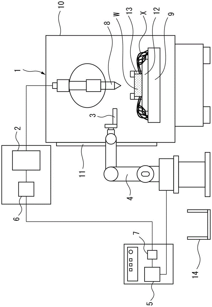
[0032] figure 1 A front view of the processing machine system of the first embodiment is shown.
[0033] refer to figure 1 , the processing machine system of the first embodiment includes: a processing machine 1, which performs dry processing or semi-dry processing; a processing machine control unit 2, which controls the processing machine 1; a robot 4, which is equipped with a chip recovery device at the front end of the robot. a hand 3 ; and a robot control unit 5 that controls the robot 4 . The processing machine system according to the first embodiment further includes a processing machine communication unit 6 and a robot communication unit 7 for communicating between the processing machine control unit 2 and the robot control unit 5 .
[0034] The machining machine 1 includes a machining tool 8 for performing machining such as drilling and cutting, and a machining table 9 for moving a workpiece W to be machined, within a housing 10 . A door 11 is provided on one side o...
no. 2 approach
[0078] Next, a second embodiment will be shown. However, here, the same reference numerals are used for the same components as those of the first embodiment, and differences from the first embodiment will be mainly described.
[0079] image 3 It is a front view which shows the processing machine system of 2nd Embodiment.
[0080] Such as image 3 As shown, the processing machine system of the second embodiment further includes a visual sensor 15 compared to the configuration of the processing machine system of the first embodiment. The vision sensor 15 is installed near the front end of the robot 4 . The vision sensor 15 images the workpiece W to be processed and its surroundings on the processing table 9 . In the second embodiment, the accumulation area and accumulation amount of chips on the processing table 9 are obtained from the image data captured by the vision sensor 15 , and the chips are collected based on the acquired accumulation area and accumulation amount. ...
no. 3 approach
[0103] Next, a third embodiment will be shown. Here, the same reference numerals are used for the same components as those in the first or second embodiment, and differences from the first or second embodiment will be mainly described.
[0104] The processing machine system of the third embodiment is equipped with image 3 The processing machine system of the second embodiment shown has the same constituent elements.
[0105] However, in the third embodiment, after the robot control unit 5 executes the chip collection program P2, the chip accumulation detection program PS1 is executed again using the vision sensor 15 to acquire the accumulation amount and accumulation area of the chips. As a result, when the accumulated amount of chips acquired is larger than a predetermined setting value, the chip collection routine P2 is executed again. In addition, such a chip collection routine P2 is repeatedly executed until the accumulated amount of chips obtained becomes smaller tha...
PUM
 Abstract
Description
Claims
Application Information
 - R&D
- Intellectual Property
- Life Sciences
- Materials
- Tech Scout
- Unparalleled Data Quality
- Higher Quality Content
- 60% Fewer Hallucinations
Browse by: Latest US Patents, China's latest patents, Technical Efficacy Thesaurus, Application Domain, Technology Topic, Popular Technical Reports.
© 2025 PatSnap. All rights reserved.Legal|Privacy policy|Modern Slavery Act Transparency Statement|Sitemap|About US| Contact US: help@patsnap.com