Robot guided oblique spinal stabilization

a robotic control and oblique stabilization technology, applied in the field of vertebral stabilization techniques, can solve the problems that the high accuracy required for oblique entry cannot be generally achieved using robotic control, and achieve the effects of low invasive spinal stabilization, less trauma, and high accuracy

Active Publication Date: 2015-03-31
MAZOR ROBOTICS
View PDF11 Cites 215 Cited by
  • Summary
  • Abstract
  • Description
  • Claims
  • Application Information

AI Technical Summary

Benefits of technology

[0013]The present disclosure describes new exemplary systems and methods for performing minimally invasive spinal stabilization, using only two screws inserted in oblique trajectories from an inferior vertebra pedicle into the adjacent superior vertebra body. The procedure can be less traumatic than some previously described procedures using oblique trajectories, by executing the trajectory drilling in a minimally invasive manner through two stab incisions, using a robotic arm to guide the surgeon along a safe trajectory. The robot arm is virtually essential in such a minimally invasive procedure since no access is provided for direct viewing of the operation site, and the high accuracy required for oblique entry can only be generally achieved using robotic control. This high accuracy level is mandated by the presence of nerve roots exiting the foramen in close proximity to the path required to proceed from the pedicle region of the inferior vertebra to the adjacent superior vertebra body. This robot guided system also obviates the need for a large number of fluoroscope images to check the drill insertion position relative to the nerve positions around the subject's vertebrae.

Problems solved by technology

The robot arm is virtually essential in such a minimally invasive procedure since no access is provided for direct viewing of the operation site, and the high accuracy required for oblique entry can only be generally achieved using robotic control.

Method used


Image

  • Robot guided oblique spinal stabilization
  • Robot guided oblique spinal stabilization
  • Robot guided oblique spinal stabilization

Examples


Embodiment Construction

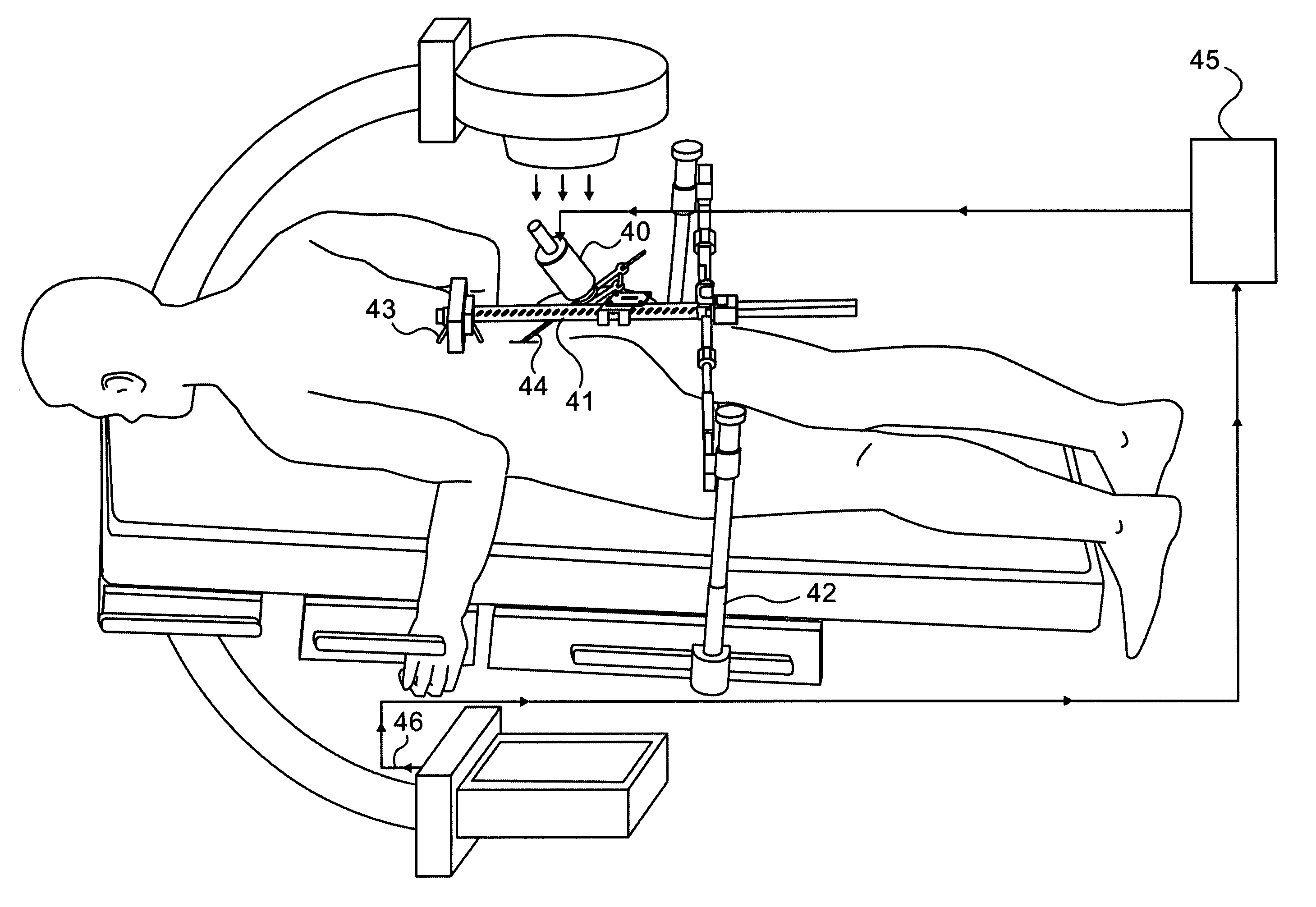
[0071]The current disclosure describes exemplary robotic devices and a robotic procedure for performing minimally invasive spinal stabilization, using only two screws inserted in an oblique trajectory from an inferior vertebra pedicle into the adjacent superior vertebra body. The procedure can be less traumatic than the previously described procedures using oblique trajectories, by executing the trajectory drilling in a minimally invasive manner through two stab incisions, using a robotic arm such as the SpineAssist supplied by Mazor Surgical Technologies Ltd. of Caesarea, Israel, to guide the surgeon along a safe trajectory. The robot arm is essential in such a minimally invasive procedure since no access is provided for direct viewing of the anatomical land marks, and the high accuracy required for oblique entry can only be generally achieved using robotic control.

[0072]Reference is now made to FIGS. 3A and 3B which are illustrations of sections of the spine showing how the nerve ...


PUM


Abstract

A robotic system for performing minimally invasive spinal stabilization, using two screws inserted in oblique trajectories from an inferior vertebra pedicle into the adjacent superior vertebra body. The procedure is less traumatic than such procedures performed using open back surgery, by virtue of the robot used to guide the surgeon along a safe trajectory, avoiding damage to nerves surrounding the vertebrae. The robot arm is advantageous since no access is provided in a minimally invasive procedure for direct viewing of the operation site, and the accuracy required for oblique entry can readily be achieved only using robotic control. This robotic system also obviates the need for a large number of fluoroscope images to check drill insertion position relative to the surrounding nerves. Disc cleaning tools with flexible wire heads are also described. The drilling trajectory is determined by comparing fluoroscope images to preoperative images showing the planned path.

Description

[0001]This is a 35 U.S.C. §371 application of PCT / IL2009 / 001130, filed Dec. 1, 2009, and claims the benefit under 35 U.S.C. §120 of said PCT application, and further claims the benefit under 35 U.S.C. §119(e) of U.S. Provisional Patent Application Ser. No. 61 / 193,441, filed Dec. 1, 2008. The contents of these priority applications are incorporated herein by reference.FIELD OF THE INVENTION[0002]The present invention relates to the field of vertebral stabilization techniques by means of a pair of obliquely inserted screws, especially using robotic procedures to safely generate the oblique entry paths between the inferior and superior vertebrae to be fused.BACKGROUND OF THE INVENTION[0003]As illustrated schematically in FIGS. 1A and 1B, a common treatment for spinal stabilization is the fixation of two or more vertebrae 10, 12, performed by insertion of a pair of screws 14, 16, into each of the vertebrae to be fused and connecting the screw heads on either side of the spine by two rig...

Claims


Application Information

Patent Timeline
Patent Type & Authority Patents(United States)
IPC IPC(8): A61B17/88A61B17/16A61B17/70A61B17/00A61B17/02A61B17/17A61B17/34A61B17/56A61B19/00
CPCA61B17/1757A61B17/1671A61B19/2203A61B17/7064A61B19/201A61B19/26A61B2017/00557A61B2017/00685A61B2017/0256A61B2017/3407A61B2019/507A61B2217/005A61B2017/564A61B17/00234A61B17/70A61B17/7074A61B17/88A61B2017/7073A61B34/30A61B90/11A61B90/50A61B2034/107A61B17/320016A61B17/3205A61B17/7001A61B2017/00261A61B2034/303A61B2090/3762
Inventor BAR, YOSSEFZEHAVI, ELILIEBERMAN, ISADORSHOHAM, MOSHE
Owner MAZOR ROBOTICS
Why Eureka
Try Eureka