Novel artwork pigment coloring sprayer
A technology of artwork and sprayer, which is applied in the field of art equipment, can solve the problems of low efficiency and achieve the effects of ease of use, improvement of spraying efficiency, and reduction of spraying time
- Summary
- Abstract
- Description
- Claims
- Application Information
AI Technical Summary
Problems solved by technology
Method used
Image

Examples
Embodiment 1
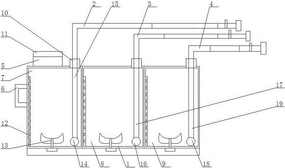
[0017] Such as figure 1 Shown, a kind of novel art paint coloring sprayer comprises paint tube 1, first spray tube 2, second spray tube 3, the third spray tube 4, controller 5, handle 6, described paint tube 1 inside It is composed of a first storage chamber 7, a second storage chamber 8, and a third storage chamber 9; the upper end of the first storage chamber 7 is equipped with the first spraying pipe 2, and the upper end of the second storage chamber 8 is equipped with the second Two spraying pipes 3, the third spraying pipe 4 is installed on the upper end of the third storage chamber 9; an electromagnetic control valve 10 is installed on the first spraying pipe 2, the second spraying pipe 3, and the third spraying pipe 4; The controller 5 is installed on the left side of the top of the paint tube 1; the upper end of the controller 5 is equipped with an LED control screen 11; the handle 6 is installed on the upper left side of the paint tube 1; the first storage chamber ...
Embodiment 2
[0019] Such as figure 1 As shown, the first liquid supply pump 14 and the first liquid supply pipe 15 are installed inside the first material storage chamber 7. The first liquid supply pump 14 is installed at the lower end of the first material storage chamber 7 and connected to the first upper end. Liquid supply pipe 15; the upper end of the first liquid supply pipe 15 is connected to the first spraying pipe 2; The left end of the first right-angle infusion tube is connected to the first liquid supply pipe 15, the right end is connected to the first telescopic hose, and the first telescopic hose is connected to the first liquid control pipe. The first liquid control pipe is connected to the first liquid spray nozzle, and a first liquid spray valve is installed on the first liquid control pipe.
Embodiment 3
[0021] Such as figure 1 As shown, the second liquid supply pump 16 and the second liquid supply pipe 17 are installed inside the second material storage chamber 8. The second liquid supply pump 16 is installed at the lower end of the second material storage chamber 8 and connected to the second upper end. Liquid supply pipe 17; the upper end of the second liquid supply pipe 17 is connected to the second spraying pipe 3; The left end of the second right-angle infusion tube is connected to the second liquid supply pipe 17, the right end is connected to the second telescopic hose, and the second telescopic hose is connected to the second liquid control pipe. The second liquid control pipe is connected to the second liquid spray nozzle, and a second liquid spray valve is installed on the second liquid control pipe.
PUM
 Abstract
Description
Claims
Application Information