A reciprocating impact mining apparatus mounted with fitted rolling guide rotation-stopping assembly blocks for implementing a guide rotation-stopping method for mounting the fitted rolling guide rotation-stopping assembly blocks

A component block and anti-rotation technology, which is applied to earth-moving drilling, cutting machinery, driving devices, etc., can solve the problems of large maintenance, frequent damage, and poor concentricity of bearing seats.

Active Publication Date: 2016-09-28
JINING CITY CUSTOMKEY ELECTROMECHANICAL TECH CO LTD
View PDF8 Cites 2 Cited by
  • Summary
  • Abstract
  • Description
  • Claims
  • Application Information

AI Technical Summary

Problems solved by technology

[0002] Due to the impact of the reciprocating impact roadheader on the coal wall, rock wall, concrete, etc. during the excavation process, the hard rock wall, concrete, etc. make the reciprocating impact part bear super strong reaction force, and the super strong reaction force has a certain impact on the reciprocating impact part. The super destructive force has resulted in frequent damage to the box seals, reciprocating impact power components, and reciprocating impact guide components of the reciprocating impact roadheader, and a large amount of maintenance. The main reasons are: 1. The support of the components is to set ear plates supporting each roller on the inner wall of the box composed of four-sided box plates. Except one side of each ear plate is connected with the box body, the rest of the parts are suspended in the air, and the ear plates are not connected to each other. Enhancing the strength of each supporting ear plate means making the ear plate bigger, which increases the volume of the box body, resulting in waste of space and material waste. Because of the poor support strength of the ear plate, the axial positioning of the roller is poor; 2. Inside the box The contact surface between the guide section and the rolling body produces partial sliding friction; 3. There are many processes in the processing of the bearing hole seats supporting more than two rolling bodies on the box, and it cannot be completed at one time by clamping one tool at a time, resulting in more than two The concentricity of the bearing seat is poor; 4. The axial positioning difference of more than two bearings makes it difficult for the axis of the two bearings to be perpendicular to the reciprocating impact guide rod after installation, so that the surface of the rolling body supported by the bearing and the reciprocating impact guide rod The surface fit is poor, resulting in a part of the surface with too large a gap, and a part of the surface is over-extruded. When the high-frequency impact of the reciprocating impact guide rod, the high temperature of the over-extruded part will cause deformation and damage to the parts, and the linearity of the reciprocating impact will be poor. The box seal section of the impact guide rod wears the box seal part, causing the seal to be damaged quickly, causing the power part in the box to generate high temperature due to the loss of lubricating and cooling fluid, and the severe high temperature deforms and damages the power part; 5. Support reciprocating The design and production of the rolling element surface of the impact guide rod and the surface of the reciprocating impact guide rod are not designed. When the reciprocating impact guide rod is subjected to a strong lateral force impact, even if the impact guide rod swings to a certain extent, the joint surface will still not The structure that produces sliding friction; 6. The design and manufacture of the surface of the rolling body supporting the reciprocating impact guide rod and the surface of the reciprocating impact guide rod has not been designed and manufactured so that when the reciprocating impact guide rod is subjected to a strong lateral force impact, the reciprocating impact guide rod The multiple sides of the rod are in a flat state and the surface of multiple rolling elements is respectively attached to the structure of rolling friction rolling guide, and the original design does not use strong control to avoid the swing of the reciprocating impact guide rod due to lateral force impact; 7. Reciprocating impact guide The rod is not equipped with a structure to widen and / or heighten the righting impact guide rod, so that the righting strength of the reciprocating impact guide rod is poor, so that the strong reaction force generated by the reciprocating impact directly acts on the reciprocating impact power components, resulting in damage to

Method used


Image

  • A reciprocating impact mining apparatus mounted with fitted rolling guide rotation-stopping assembly blocks for implementing a guide rotation-stopping method for mounting the fitted rolling guide rotation-stopping assembly blocks
  • A reciprocating impact mining apparatus mounted with fitted rolling guide rotation-stopping assembly blocks for implementing a guide rotation-stopping method for mounting the fitted rolling guide rotation-stopping assembly blocks
  • A reciprocating impact mining apparatus mounted with fitted rolling guide rotation-stopping assembly blocks for implementing a guide rotation-stopping method for mounting the fitted rolling guide rotation-stopping assembly blocks

Examples


Embodiment 1

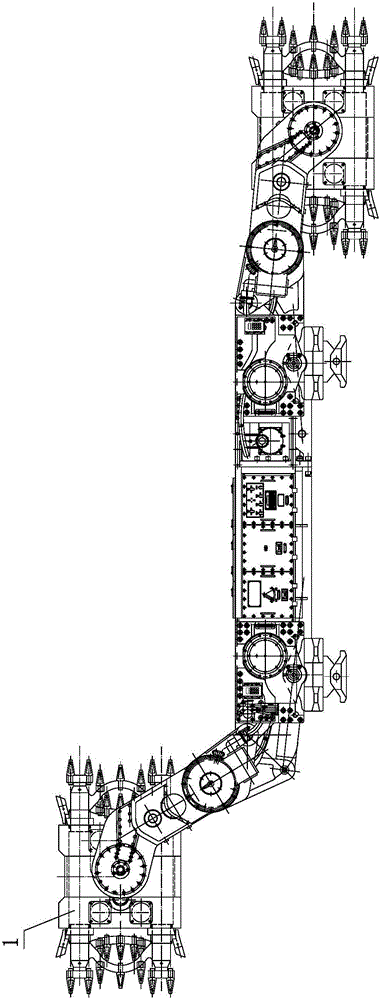
[0212] Such as Figure 1 to Figure 6 As shown, it is the reciprocating impact excavator equipped with rolling guide and anti-rotation assembly blocks according to the rolling guide anti-rotation assembly block guide anti-rotation method shown in Embodiment 1. The rolling guide anti-rotation assembly block reciprocating impact mining machine includes linkage guide Sealed sprocket seat 5, reciprocating power unit 9, rolling guide stopper 44, rolling guide stop assembly block 1, integrated block connector 26, guide stop box seal and reciprocating punching tooth 8, etc., interlocking guide seal The gear insertion seat 5 includes a reciprocating tooth seat interlocking section 73, a reciprocating tooth seat guiding section 33, a reciprocating tooth seat sealing section 71, a reciprocating tooth seat inserting section 72, etc. 1. The reciprocating tooth seat sealing section 71 and the reciprocating tooth seat inserting section 72 are integrated, and the front end of the interlocking...

Embodiment 2

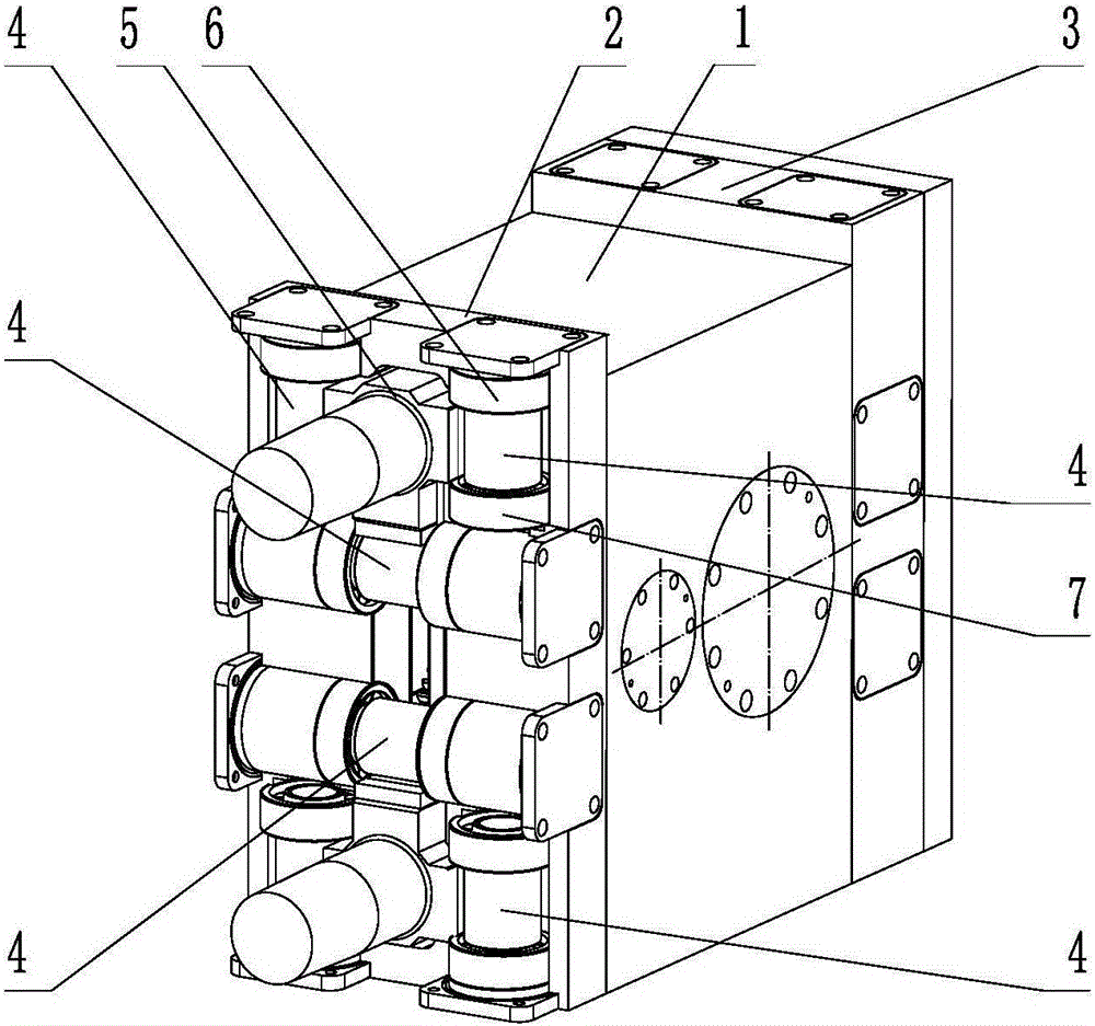
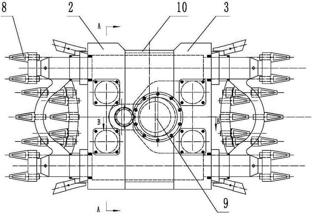
[0228] Such as Figure 7 to Figure 11 As shown, it is the reciprocating impact excavator equipped with rolling guide anti-rotation assembly block shown in embodiment 2. The difference from embodiment 1 is that the front end of the interlocking guide seal gear holder 5 is provided with a reciprocating gear holder gear section 72. The single gear holder, the reciprocating punching gear 8 is arranged at the front end of the interlocking guide seal gear holder 5, the reciprocating power device 9 is a camshaft mechanism 17, and the camshaft mechanism 17 includes a crank connecting rod 16, etc. When the camshaft mechanism 17 is used, The crank connecting rod 16 is hinged with the interlocking guide seal pinion seat 5, and a connecting rod 282 drives a single pinion seat to form a single pinion seat reciprocating impactor. The rolling guide stopper 44 includes the roller guide stopper 11. The shaft-guided anti-rotation device 11 includes bearing A6, bearing B7 and guide roller 4, etc...

Embodiment 3

[0233] Such as Figure 12 , Figure 13 As shown, it is the reciprocating impact excavator equipped with rolling guide anti-rotation assembly block shown in embodiment 3. The difference from embodiment 1 is that the guide roller 4 is provided with bearing A inner ring stopper 42 and bearing B inner ring stopper Platform 43, etc., the diameter of bearing A inner ring stopper 42 is larger than the inner hole of bearing A6 and smaller than the inner diameter of bearing A6 outer ring, the diameter of bearing B inner ring stopper 43 is larger than the inner hole of bearing B7 and smaller than the inner diameter of bearing B7 outer ring, the inner diameter of bearing A inner ring The block 42 and the block 43 of the inner ring of the bearing B block the movement of the bearing A6 and the bearing B7 along the guide roller 4, and the rolling guide stopper 44 includes an anti-rotation part of the bearing, and the anti-movement part of the bearing includes a bearing sleeve 37 and an end ...


PUM


Abstract

The invention belongs to the field of machinery and particularly relates to a reciprocating impact mining apparatus mounted with fitted rolling guide rotation-stopping assembly blocks for implementing a guide rotation-stopping method for mounting the fitted rolling guide rotation-stopping assembly blocks. The mining apparatus comprises linked guide sealed tooth-inserting bases, a reciprocating power device, rolling guide rotation-stopping devices, fitted rolling guide rotation-stopping assembly blocks, an integrated block connecting piece, a guide rotation-stopping box sealing piece and reciprocating impacting teeth. The reciprocating impacting teeth are disposed at front ends of the linked guide sealed tooth-inserting bases. A connecting rod drives a single tooth-inserting base to form a single-tooth-inserting base reciprocating impact device. The fitted rolling guide rotation-stopping assembly blocks increase guide cohesive force and guide uprighting force. A plurality of supporting ear plates supporting a plurality of the rolling guide rotation-stopping devices are formed as an integrated plate through the fitted rolling guide rotation-stopping assembly blocks. The integrated plate enables intensification and substantialization of a space required by supporting the plurality of the rolling guide rotation-stopping devices and improves the positioning precision of the plurality of rolling guide rotation-stopping devices.

Description

technical field [0001] The invention belongs to the field of machinery, and in particular relates to a reciprocating impact excavator with a rolling guide and anti-rotation assembly block for implementing a rolling-guiding anti-rotation assembly block-installed anti-rotation method. Background technique [0002] Due to the impact of the reciprocating impact roadheader on the coal wall, rock wall, concrete, etc. during the excavation process, the hard rock wall, concrete, etc. make the reciprocating impact part bear super strong reaction force, and the super strong reaction force has a certain impact on the reciprocating impact part. The super destructive force has resulted in frequent damage to the box seals, reciprocating impact power components, and reciprocating impact guide components of the reciprocating impact roadheader, and a large amount of maintenance. The main reasons are: 1. The support of the components is to set ear plates supporting each roller on the inner wa...

Claims


Application Information

Patent Timeline
Patent Type & Authority Applications(China)
IPC IPC(8): E21C25/02E21C25/04E21C25/68E21C35/20E21C35/08E21C31/02E21C35/18E21C35/19E21C35/183E21C35/22E21C35/00E21D9/10
CPCE21C25/02E21C25/04E21C25/68E21C31/02E21C35/00E21C35/08E21C35/18E21C35/183E21C35/187E21C35/19E21C35/20E21C35/22E21D9/106E21D9/1086E21D9/1093E21D9/12E21C25/00E21F13/00
Inventor 刘素华
Owner JINING CITY CUSTOMKEY ELECTROMECHANICAL TECH CO LTD
Why Eureka
Try Eureka